Greetings 2026! As expected, EV demand has waned following some deregulation and tax credits being dropped as of September 2025. For us industry folks, this is simply reality catching up with the narrative. On the plus side, 2025 was a very good year for global vehicle sales–the best since 2019 (Ref. 1). A good economy can forgive many blunders. As gearbox designers, our work continues as our EV offerings are likely a permanent part of our product lineup, even if at a reduced volume.

Due to the need for mass reduction, tight packaging, and overall car performance, it is necessary to reduce the weight and dimensions of every component of the car, including the gearbox and other drivetrain components. It is also very important to ensure that gears, bearings, and shafts can withstand the whole racing season and have the necessary safety factor. Using KISSsoft software, FSB Racing Team was able to develop a new gearbox for the AWD Formula Student car, which can easily fit inside upright and withstand 50 hours of racing.

For worm gearboxes, oils are mainly used in combination with splash lubrication. Consistent lubricants, such as greases, are used less frequently and are used, for example, in gearboxes where it is not possible or difficult to seal the housing (Ref. 1). These applications include positioning gears, but also power gears with high sealing requirements, such as in the food industry. Grease lubrication has, in comparison to oil, a negative thermal effect on the worm, resulting in higher mass temperatures (Ref. 2). However, this effect becomes less relevant in the application of positioning gears, so that the advantages of grease lubrication outweigh the disadvantages in these applications.

For over two decades, our Montreal-based engineering simulation consultancy has provided advanced solutions to a diverse range of industries. Our expertise has facilitated the resolution of complex engineering challenges, leveraging the latest technologies in computational fluid dynamics (CFD) and heat transfer analysis. Among our recent projects, one particularly notable case involved a company specializing in converting combustion engine vehicles to electric vehicles.

Loaded tooth contact analysis of gears, considering or neglecting gear misalignment, may be performed by gear design software such as KISSsoft or other similar tools. Approximately a dozen such commercial software programs are used in an international environment, most of them based on analytical approaches. Very few are based on FEM approaches.


Sometimes corrosion is attractive. For example, the vivid colors on titanium jewelry are oxides, with the color difference the result of the oxide thickness and the refracted light. Also, from an artistically oriented viewpoint, the golden-brown appearance of many of the new high-voltage towers made from ASTM A 242 (Corten) steel is more appealing than their bright galvanized cousins, and that “pleasing brown color” is a tightly bonded coating of rust. But most of the time, and in several ways, corrosion presents difficulties that can greatly shorten the life of mechanical equipment.

Bearing damage due to electric current in variable frequency drives (VFD) is well understood as a general concept. What is not yet fully developed are the models that better predict when a system is at risk and where we should be looking for early signs of damage.

Stepper motor linear actuators (SMLAs) combine a stepper motor, precision lead screw and nut in one compact envelope, providing a highly configurable, customizable and robust solution for linear motion. With the help of a motion controller and a stepper driver, all SMLAs can be programmed to position a load to a precise location. However, standard configurations do not provide a feedback mechanism that tells the operator whether the move is completed or not.
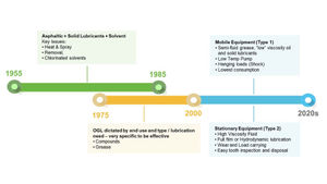
Lubricating greases are typically known for their use in a wide variety of applications such as rolling element bearings, automotive transmission joints as well as heavy duty chassis components; but can also be found very useful in the lubrication of gears. There are two types of gear families: the primary difference being open and enclosed gearboxes. The gears within a closed system are lubricated with grease within the system. Open gears are lubricated by grease or fluid separate from the piece of equipment. This paper will focus on the lubrication of open gears, utilizing both grease and fluid Open Gear Lubricants (OGL).

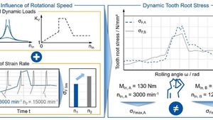
Tooth contact analysis is an integral part of the gear design process. With the help of these simulation tools, it is possible to calculate the excitation caused by a tooth contact (Ref. 1). Usually, the load-free transmission error or the total transmission error under load is used for this purpose. However, the calculation with the tooth contact analysis ZAKO3D allows only a quasi-static consideration of the excitation. To better evaluate the behavior in the overall system, it is therefore necessary to perform a dynamics simulation. However, the main disadvantage of such dynamics simulations is the much longer computing time compared to quasi-static tooth contact analyses due to the high computational effort.

Closed-loop control systems can handle a wide range of motions with a wide range of loads if the control system and the mechanics of the system are properly designed for the task. A couple of the more difficult combinations to design for are high inertial mismatches and backlash with hard gearing. The question is not just how to make the system stable but also how to get the desired performance.

Closed Loop control systems can handle a wide range of motions with a wide range of loads if the control system and mechanics are properly designed for the task. A couple of the more difficult combinations to design for are high inertial mismatches and backlash with hard gearing. The question is not just how to make the system stable, but rather how to also get the desired performance.

I would like to briefly discuss some thoughts on ball bearing efficiency specifically in terms of applied load and resulting stress. I don’t want to trivialize this subject; there are textbooks written on the subjects of electrohydrodynamic lubrication (EHL), octahedral subsurface shear stress and friction losses due to elastic hysteresis. This is a just a high-level discussion on the importance of individual bearing stress on efficiency.

UGRacing is the University of Glasgow’s Formula Student team. Since its inception in 2005, the team has been working to compete at Formula Student UK (FSUK). Over the last decade, the team has grown to over 150 members across ten disciplines. With a strong focus on knowledge transfer and iterative design, the team has worked year after year to develop new technologies and a more refined package. In 2022, the team saw a culmination of all their hard work when they placed first overall in FSUK with their final internal combustion vehicle. The following switch to an electric powertrain brought new challenges. Through the constraint of a new powertrain architecture, the team has explored and innovated drivetrain concepts which, in future years, will improve vehicle performance.

Have you ever been confused about pipe thread nomenclature? Have you wondered what is the difference between NPT and PT? What about BSPT? If you have asked these questions or similar ones, you’re not alone and this paper is for you! Several different pipe thread designations are used around the world, and some are equivalent or compatible while others are not.

Verification of a drive system should include all main elements of the system, which are gears, bearings, shafts, and depending on the application other parts such as screws, couplings, and connections. Gears are clearly the most complicated parts for verification, but in many cases, a gearbox failure has its origin in a shaft or bearing failure. The subject of this paper is to explain how verification of a drive system based on measured or simulated torque-speed-time data can be handled.


For this paper, the digital twin refers to a digital asset that exists alongside the physical asset during its operational life, providing insight into and feedback on the physical asset’s performance and health. Thus, the focus is on the DTI, with the potential to aggregate data into a DTA for the gearbox design being considered, and within the DTE set up by Hexagon.
In respect of the physical asset across its life, nothing is more important about its performance than its ability to function, i.e., reliability, and for CAE, nothing is of greater importance than to be able to predict the reliability of a product being designed. Thus, for this study, whilst gearbox noise, efficiency, and thermal behavior may be of interest, the primary interest is fatigue and reliability.

When motion system designers need complex, high-speed, multiaxis motion, they might first think of elaborate, prepackaged robot arms. Or, if they need only a few axes, they might configure a separate profile or round rail for each axis. But hiding between those options is simple and proven ball spline technology. This multiaxis motion solution has existed for years and is still highly relevant to today’s complex motion schemes. Ball splines use a unique architecture integrating rotary and linear motion on a single shaft. This gives them more flexibility to implement complex motion schemes in tighter spaces, providing a two-for-one deal in motion control.

Steel, iron, and aluminum are the dominant materials in the mechanical power transmission industry for good reason: high power density requires the high strength and stiffness of metallic materials. Plastics, however, offer valuable features that should be utilized for good gearbox design.

Modern spindle applications of rolling bearings require very high speeds and very high loads, often combined with poor lubrication conditions and/or high solid contamination. Examples of these applications are high-speed and high-cutting rate machine tools, where rolling bearings need to survive very though conditions. Rolling bearings in high speed and high load conditions might suffer from poor lubrication and potentially surface distress and adhesive wear.


Randy Stott, publisher of Power Transmission Engineering and Gear Technology magazines, recently sat down with Norm Parker, technical fellow and technical manager for Torque Transfer Systems at Stellantis, to discuss bearing technology during the Motion + Power Technology Expo in Detroit.

Why use the rolling process to produce high accuracy lead screws, actuator screws, and other power transmission components rather than traditional cutting processes such as turning, grinding, milling, whirling, or hobbing? Rolling processes and cutting processes both produce a precise form on the workpiece. But if the form geometry, tolerances, and material selection allow, rolling is the process to beat. Speed, surface finish, fatigue strength, precision, dimensional stability, and material savings are some of the primary advantages realized when the rolling process is applied.

This report derives the equation for relative elastohydrodynamic lubrication (EHL) film thickness. Mineral (MIN), polyalphaolefin (PAO), and polyalkylene glycol (PAG) lubricants with viscosity grades of ISO 320, 150, and 32 are analyzed.

More energy efficiency, higher performance and better controllability are the main reasons why more electric drive systems are being operated with frequency converters. However, these devices can cause high-frequency, asymmetrical interference currents, which, as a current passage through the output and fan-side bearings, can cause damage and premature failure.
Current-compensated CoolBlue toroidal cores made of Magnetec’s nanocrystalline material Nanoperm have proven to be effective protection against such conducted interference and its consequences. In addition, the Nanoperm Line Absorbers NaLA can also be used to significantly suppress symmetrical interference currents.

Rolling bearing calculations are usually based on the assumption of ideal nominal geometries. However, actual components and assemblies are always subject to statically distributed geometric deviations resulting from the manufacturing and assembly processes. This leads to changes in the internal geometric conditions which have an effect on bearing characteristics such as the service life. The FVA-Workbench makes it possible for users to consider these geometric deviations in bearing calculations for more reliable results.

Technical sales personnel use intelligent features to select suitable motor-gearbox combinations and run calculations based on customer-specific operating data. This provides obvious added value for the customer. Service lives, safeties, and expected loads can all be determined in a short time. Maintenance of the underlying database and the use of simulation tools make it possible to quickly and easily perform technical calculations without having to rely on a central calculation department. In less than a minute, the customer is provided with a data sheet which includes reliable statements about the gearbox based on these technical calculations.

This review of Ref. 1 summarizes the conclusions of test data and numerical simulations showing that Stribeck curves for counterformal contact are different from Stribeck curves for conformal contact.


Welcome back to Part 2 of our inner ring and creep discussion. We left off with our creep calculation resulting in a 10.5 µm minimum inner ring fit to avoid creep. For the sake of making clean dimensions, let’s call it 10 µm on the lower end and the upper end is simply whatever your manufacturer can hold.

The earliest example of a gear train dates to at least 2,000 B.C. when Chinese engineers built a chariot that used a complex planetary mechanism made of wooden gears to let a dragon head continuously point south when driven around (Ref. 1). In Greece, a surprisingly advanced Antikythera gearbox mechanism, incorporating at least 37 precisely crafted bronze gears, was built years later, between 205–60 B.C. (Ref. 2).

This study presents a simulation method for considering complex wheel bodies in an analytical tooth contact model. The wheel body is considered using reduced FE stiffness. Reduction points are defined over the width and linked with the analytical gear.
For cylindrical wheel bodies, comparative calculations show fewer deviations from the expected results with the new method. This is due to the additional degrees of freedom in the FEM model. In the calculation with cylindrical wheel bodies, bending due to axial force in tooth contact could also be verified in addition to the deformation in tooth contact and the influence of the shaft-bearing system.

I think I spend more time talking about ball bearings today than at any other time in my career. Ball bearings have always had a large place in automotive, but not typically in high demand positions—other than a few niche areas. High demand positions, such as axles and planetaries, were typically reserved for tapers, needles and cylindricals. The landscape is changing quickly.

This article is Part III in a series of articles on speed rating of bearings. Part I appeared in the September 2022 issue ("Ball Bearing Limiting Speeds"), and Part II appeared in the October 2022 issue ("Ball Bearing Thermal Speed Rating"). Bearings with Norm examines the latest in bearing technology and design.

Today, gearboxes are inevitable in numerous applications requiring high power density including wind turbines, electric vehicles, cranes, robotics, etc. A combination of high-ratio gearboxes with high-speed, low-torque motors is often used to achieve high power density. Planetary gear trains (PGTs) help achieve a high gear ratio in a compact arrangement. Several configurations of planetary gears are widely studied in this article where the gear profiles used in these studies are primarily involute.

The goal of increasing the power density of a gear unit demands that extraneous material reserves can be detected and reduced to the necessary level. In this context, it is important to know the influences acting on the gear unit and the resulting loads. FVA examines the precise knowledge of the longitudinal load distribution in the gear meshes during operation, and specification of suitable microgeometries for its optimization, play a decisive role.

When your equipment calls for a right angle gearbox, proper sizing makes a difference. A wide range of application factors must be considered, or you will face problems down the road. Possible problems can include increased maintenance, worn teeth and reduced mean time between failure (MTBF). Additionally, an oversized gearbox will cost more money than necessary. This article will provide an overview of how to apply application information to accurately size an Andantex Anglgear right angle gearbox for your installation.


Stöber Antriebstechnik GmbH + Co. KG rely on the FVA-Workbench for dimensioning and verification of their drives. The calculation and simulation software allows Stöber engineers to develop their innovative gear unit solutions more quickly and efficiently. The result: higher quality products.


In the past, we designed motors and drives separately from the mechanical system, and then we integrated suitable components to make a system work. Increasingly, though, the design focuses more on the overall system aspect and system integration, which makes the design of customized components more challenging. In this article, we will use examples of specific software tools, and it should be noted that these are just that: examples. For many of these tools, multiple similar and good software packages exist that can be used.

A quick search of the patents issued, as well as a review of recent articles, shows a wide range of what authors call “servo stepper motors,” “closed-loop step motors,” “hybrid servo motors” and the like. Although the names may sound similar, the performance can vary quite substantially. Most of the “closed-loop stepper motors” are not actually servo motors!

The technical division of AGMA directs the committees that develop and maintain standards and information sheets pertaining to the gear industry. Although often viewed as an accessory for gearboxes, flexible couplings are critical components of any machinery system, since they connect two separate pieces of rotating equipment. The Flexible Coupling Committee is responsible for 12 standards and one information sheet that are specific to flexible couplings. Six of those standards encompassing three subjects will be highlighted in this article.

As well as evaluation of profile, helix and pitch deviations, harmonic analysis of measured 2D trace data is routinely used by some industries to control gear noise and characterize machine tool performance. Evaluation of 3D surface measurement data has not been investigated.


![]()
![]()
Contact | Privacy Policy
©2026 Power Transmission Engineering
 Power Transmission Engineering is THE magazine of mechanical components. PTE is written for engineers and maintenance pros who specify, purchase and use gears, gear drives, bearings, motors, couplings, clutches, lubrication, seals and all other types of mechanical power transmission and motion control components.