Ball Bearing Inner Ring Fits and Creep
Figure 1—Outer ring creep of differential tapered bearings.
I think I spend more time talking about ball bearings today than at any other time in my career. Ball bearings have always had a large place in automotive, but not typically in high demand positions—other than a few niche areas. High demand positions, such as axles and planetaries, were typically reserved for tapers, needles and cylindricals. The landscape is changing quickly. Along the rotor shaft of an electric powertrain, ball bearings and cylindricals are the most popular choices to handle the high-speed demands, often accompanied with high load demands from the first reduction gearset. The cycle count demands of these bearings are like traditional valvetrain bearings. Whenever the vehicle is moving, these bearings are in motion and taking load. Depending on the gear ratio and type of vehicle, cycle counts north of a billion are not out of the question. Over the life of a heavily loaded bearing of any sort, some amount of turning on the shaft and housing are not uncommon. Light indications of turning that aren’t plowing and damaging material are generally considered harmless. If the turning is substantial, it can create heat, wear, and become a real issue. This annoying reality that we must deal with is referred to as creep. There are a few different mechanisms that can cause creep which we will cover in depth another time. Much of the literature you will read only talks about outer ring creep, but inner ring creep is just as common and can be more troublesome.
The ball bearing design process starts with inner ring fits and if you mess this part up in the beginning, it can be difficult to fix later.
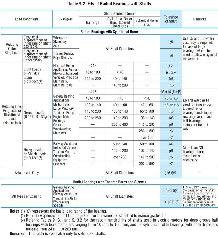
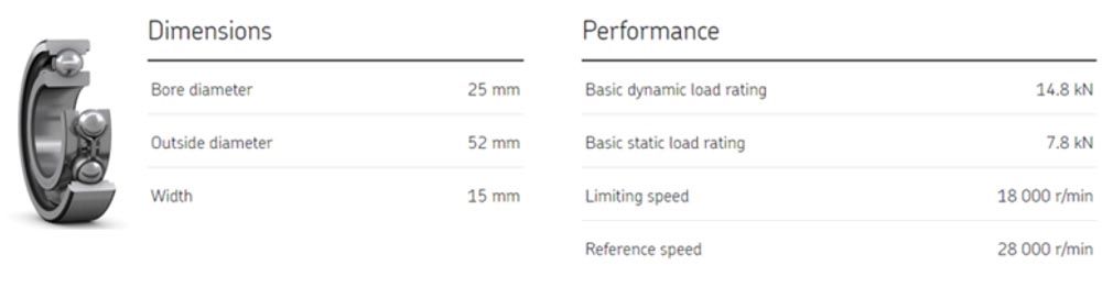
In every bearing catalog, you will start with a table that looks something like this:
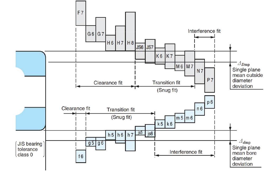
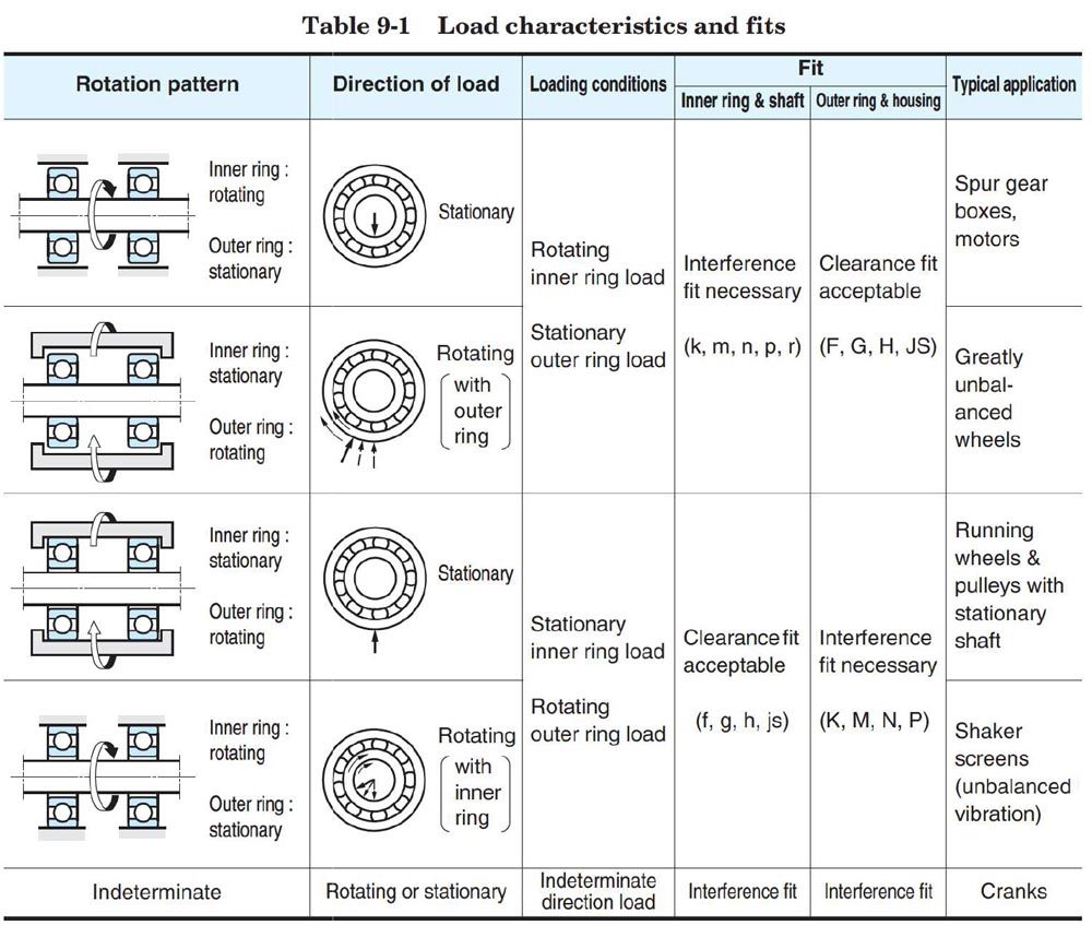 Figure 2—JTEKT Co. Cat B2001E-3 Ball and Roller Bearings Table 9-1 p.A80
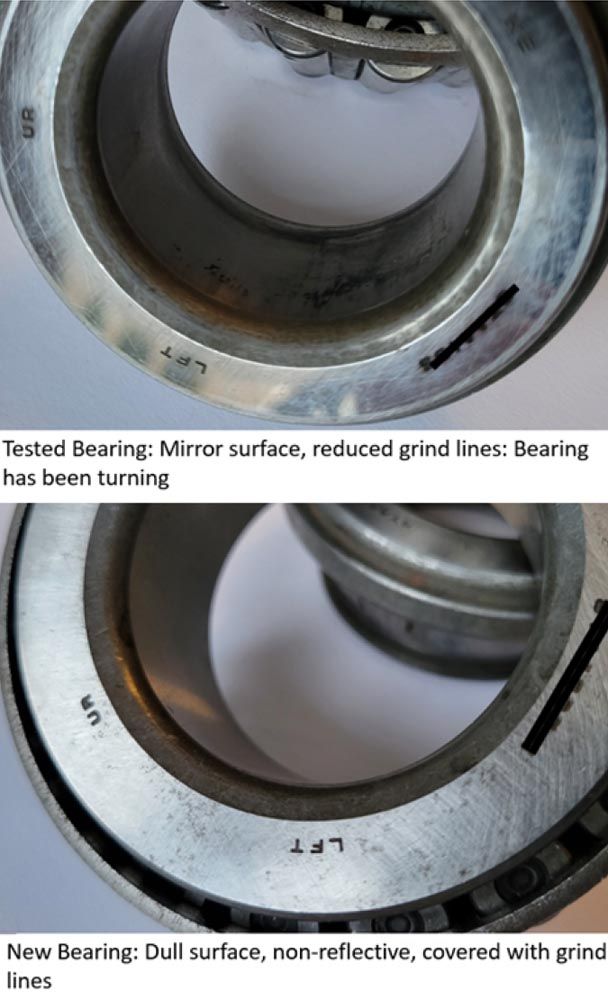
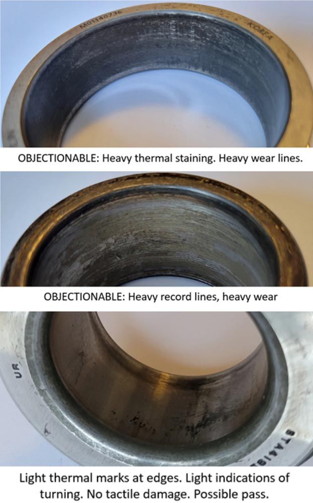
If you are not used to the nomenclature, gearboxes of any sort have a rotating inner ring load (the load is being delivered by the shaft), opposed to a wheel bearing which has a rotating outer ring load. This takes us to the first row of the table (above) which calls for an interference fit on the inner ring and a clearance fit on the outer ring. I get asked frequently why we have a clearance fit on the outer ring and won’t it spin in the housing? For a non-sealed bearing in an oil fed system, the answer is, you may see some light evidence of turning, but not enough to move material and/or create any type of damage. The reason why this is the case is because the bearing is usually loaded, pressing the outer ring into the housing. When we go from drive to coast or regeneration, the bearing load is briefly lifted, and the bearing may turn a little during this transition time, but no load means no damage. When the bearing is loaded, it is only the tractive force of the rollers trying to move the outer ring. There are times when this still can be an issue, but most of the time it is not. Inner rings aren’t always so obvious. I have had rings turn that had no business turning. The loads were light, the fits were substantial. Or other times, the loads were substantial, but the press fits were outrageously high. Sometimes you simply cannot get it to completely go away. It is good to have a pre-established plan for what to call acceptable and not acceptable. Many bearing engineers like the crude fingernail test. If you can feel it with your fingernail, it’s not great. First, determine if the bearing has been turning. On a ball bearing, there will often be some obvious abrasion on the inner ring or polishing of the surfaces. After test, if the bearing bore, shaft, or parts of the bearing seem unusually shiny, it likely has been turning. The photograph (third column, top) is a taper, but was a good example of a bearing that was obviously turning, but didn’t damage any mating components.