A recommendation for the transmission ratio distribution for two-stage gearboxes under acoustic target aspects does not exist so far. Possible approaches are the consideration of the technical consonance with which the occurrence of the excitation orders of both stages can be classified as pleasant or annoying. Existing work is limited to the interaction of an electric motor and a single-stage gearbox or several electric motors (Refs. 21–22).
Objective and Approach
As the state of the art shows, methods are frequently used in gear design that focus on single gear stages, and that the interaction between the stages is neglected when characterizing the excitation behavior. They also use quasi-static approaches or approximations based on macrogeometry. Due to the high drive speeds applied in e-mobility, the dynamic excitation behavior is dominated by the gear mesh frequencies in wide speed ranges. Possible load increases due to the coincidence of excitation frequencies and system resonance cannot be taken into account. Early and precise knowledge of the dynamic excitation behavior over the entire speed range should be sought in the sense of frontloading to reduce design and adjustment costs.
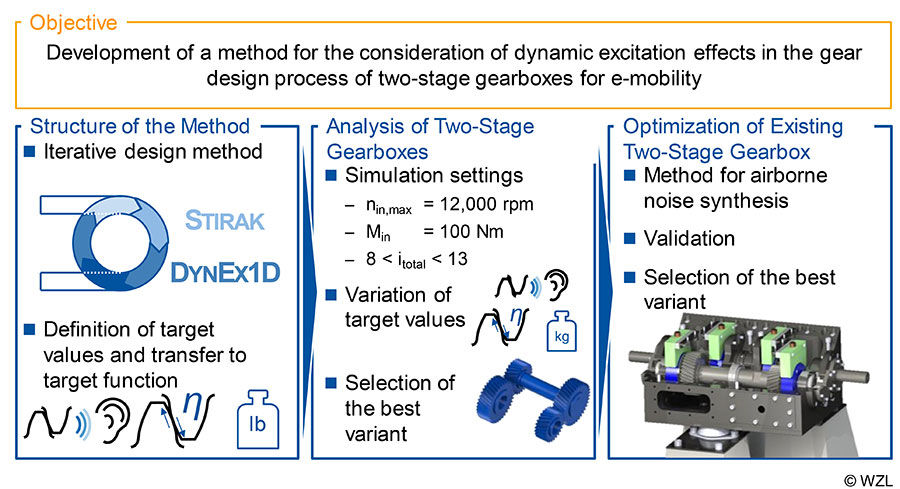
The objective of the present report is therefore to consider dynamic excitation effects in the gear design of two-stage gearboxes for e-mobility (Fig. 3). The objective is based on the research thesis that the design quality can be increased in an early development stage by considering dynamic excitation effects. This includes, on the one hand, the consideration of occurring system natural frequencies, as well as the interactions between the gear stages on the other.
Figure 3: Objective and approach.
At first, a design method is developed that combines the macrogeometric gear design with the simulation of the dynamic excitation behavior. For the evaluation of the dynamic excitation behavior, the simulation software DynEx1D is used, which considers the gear mesh with the force coupling element GearForce1D according to Gacka and the drive train as torsional vibration system (Ref. 13). The difference velocities of the two gear stages at a speed run up to nin = 12,000 rpm are selected as evaluation variables. A particle swarm algorithm based on the swarm behavior of birds is used to reduce the computing time (Ref. 24). In the design method, the variants are evaluated with regard to load-carrying capacity, dynamic excitation behavior, mass, tonality according to DIN 45681 and degree of loss (Ref. 3).
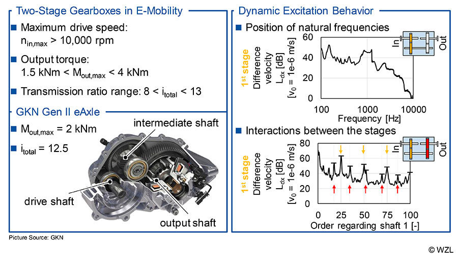
The method is then used to design new, two-stage gearboxes for e-mobility, to compare different target values and to identify the best variant. The total transmission ratio of the gearboxes is in the range according to e-mobility application between 8 ≤ itotal ≤ 13. The dependency of the optimum transmission ratio distribution between the gear stages on the mass is also investigated and compared with recommended transmission ratio distributions from the literature. The last step is the application of the method to an existing two-stage gearbox whose acoustic behavior is to be improved (Ref. 25). The developed method will be extended by quantifying the transfer behavior between the excitation in the gear mesh and the resulting airborne noise on the basis of measurement results. The determined transfer function is applied to the simulation results and the resulting airborne noise is used to evaluate the variants.
Structure of the Design Method
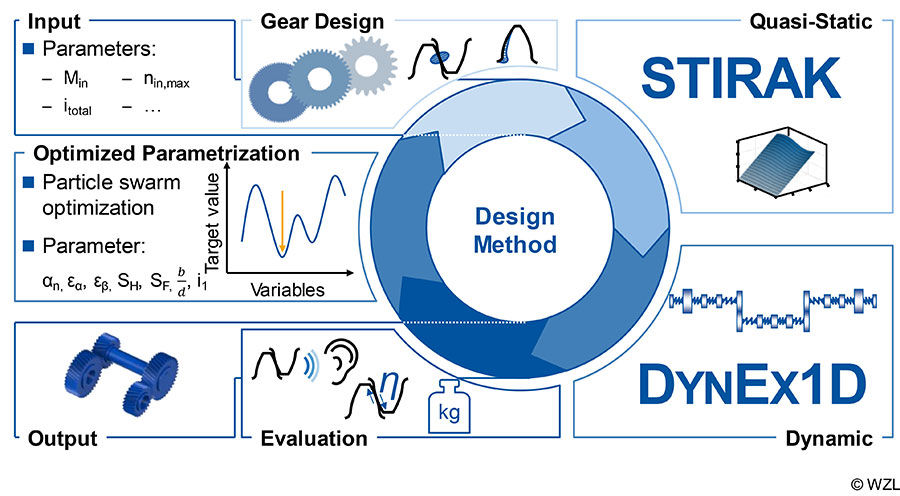
The excitation and noise behavior of gearboxes is decisively determined by the interaction between excitation in gear mesh and the system behavior of the drive train (Ref. 26). Therefore, a design method is developed which combines the macrogeometric design of the gears with a dynamic simulation of the excitation behavior. The iterative procedure is shown (Fig. 4). The input torque Min, the total transmission ratio and other variables, such as the maximum drive speed, are required as input parameters. The boundary conditions are also specified. These include in particular the parameter ranges of the variation parameters and the weighting factors for the evaluation. In the present design method, the pressure angle αn, the contact ratios εα and εβ, the width-diameter ratio b/d1 and the transmission ratio distribution are specified for both stages. In addition, further parameters like the center distance can already be specified if they are not freely selectable due to an existing concept. Based on the input variables and boundary conditions, the gears are designed in the first step. For this purpose, center distance a and module mn are determined according to ISO 6336 based on the Naunheimer procedure (Refs. 5, 10, 8). The safety against pitting and tooth root fracture is necessary criteria and are not used as quality criteria in the later evaluation. Variants that fall below the required minimum safety are sorted out in this step. This also includes variants which have undercut, too little tip clearance or too little tooth tip thickness and whose largest common divisor of the number of teeth is greater than one.
Figure 4: Procedure for the design method.
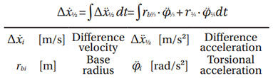
In the second step, the quasi-static characteristic maps required for further dynamic analyses are calculated for the possible variants with the aid of the FE-based tooth contact analysis FE Stirnradkette (Stirak). Due to the varying diameter in the profile and width direction of the gears, no fixed number of FE-elements is defined in the respective direction. Instead, the element size is determined dynamically as a function of the existing gear. With a view to reducing calculation time, an FE mesh that is as coarse as possible is selected. The third step is the dynamic calculation of the variants. For this purpose, the simulation program DynEx1D, which is described in detail in the next section, is used to calculate speed run-ups. For further evaluation, the difference velocity of the two gear stages corresponding to the temporal integration of the difference acceleration is selected, cf. equation 1.
The evaluation and comparison of the variants are carried out on the basis of different target values. These include parameters for dynamic excitation behavior, tonality according to DIN 45681, mass and efficiency (Ref. 3). The description of the different target values and the combination of a target function are described later. New values are assigned to the variation parameters on the basis of the target function. For this purpose, the particle swarm analysis is used to assign new values to the parameters within the boundary conditions defined at the beginning. The algorithm of the particle swarm analysis originates from the class of the nature-analog algorithms and was derived from the swarm behavior of birds. The objective of the algorithm is to minimize a given fitness function, in this case, the target function. The variation of each particle depends on a cognitive, a social and a stochastic component. Thus, each particle strives to find the minimum in the spanned search space (Ref. 24). The iterative design method is performed up to a defined termination criterion that corresponds to the maximum number of iterations. The best variant can then be identified.
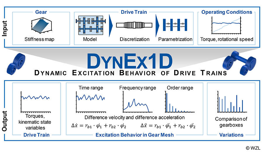
Dynamic simulation model. DynEx1D can be used to calculate the dynamic excitation behavior of multi-stage gearboxes. DynEx1D consists of two main components: The GearForce1D force coupling element according to Gacka developed at the WZL of the RWTH Aachen and the drive train regarded as a multi-body simulation model in the rotational degree of freedom (Ref. 22). The dynamic drive train behavior and the gear excitation can be calculated by the interaction of the two components. The input variables required are stiffness maps of the gears, the drive train structure and the operating conditions such as torque and rotational speed curves (Fig. 5). The stiffness maps can be determined with the FE-based tooth contact analysis Stirak (Ref. 26).
Figure 5: Performance scope of DynEx1D.
The drive train is mapped as a multi-body simulation model and considered as a torsional vibration system. For the determination of realistic natural frequencies and shapes, the complete test setup from the drive to the driven machine can be considered. The procedure for mapping the drive train in the MBS environment has the goal of providing the system matrices (mass inertia, stiffness, damping) for the simulation. The drive train is divided into a system of discrete mass inertias, which are connected by massless spring/damper systems. The numerical values of the parameters are then determined and used as input by the calculation core.
In order to avoid extended, costly calculation times and numerical inaccuracies, a modal reduction of the degrees of freedom according to Craig and Bampton is performed as a first step in the calculation core (Ref. 27). The force coupling element GearForce1D receives the kinematic conditions (angle of rotation and speed) from the dynamic drive train model as input variables in each time step and returns the excitation forces to it. The excitation forces consist of a variable tooth stiffness component and a damping component. The tooth stiffness is taken into account via the stiffness maps from Stirak mentioned above, of which the output values are the occurring forces and torques as a function of the current angular position and the load-caused transmission error of the gear. In contrast, the damping component is included via a speed proportional approach according to Gerber (Ref. 28).
The torque of the drive train and the rotation angles and speeds of input and output drives, gears and measurement systems can be selected as output values. However, the main focus of the software is on the gear mesh and the difference velocity and acceleration in the time and frequency domain. DynEx1D also enables variant calculations, taking into account the dynamic excitation behavior, to compare different gear stages and to identify the best variant on the basis of single-number values.
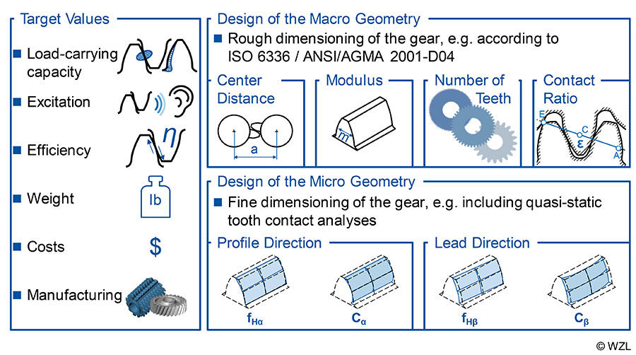
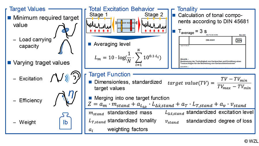
Target values. The evaluation of the variants can be carried out with regard to different target values. As mentioned at the beginning, sufficient load-carrying capacity and the associated operational safety represent a necessary criterion, which is not included in the quality assessment but is included as a minimum requirement. Instead, the target values considered in the design method can be subdivided according to excitation, efficiency and weight (Fig. 6, bottom right).
Figure 6: Definition of target values.
The dynamic excitation can be evaluated both on the basis of the total excitation and on the basis of the tonality, according to DIN 45681 (Ref. 3). The total excitation is quantified on the basis of the dynamic simulation results of the difference velocity of the two gear stages.
For this purpose, the averaged order spectra of the speed run-up are determined for each gear stage. The energetically averaged excitation levels are then determined for the first four gear mesh orders of the first stage and the gear mesh orders of the second stage lying within this order range (Fig. 6). The total excitation level results from the energetic averaging of the two stages, so that this single-number value can be used for the evaluation of the total excitation.
The analysis of the tonality according to DIN 45681 allows a statement to be made about the occurrence of tones in the overall noise (Ref. 3). The metric was developed for airborne noise signals. To compare and classify different variants, however, it can also be applied to the difference velocity without comparing the absolute tonality values of the two different physical basic quantities. During the calculation, the total signal is divided into averaging intervals with a duration of Taverage = 3 s and checked whether frequencies emerge and lead to psycho-acoustically perceptible tones.
Efficiency is used as the ratio of output power to input power. The complement to the efficiency is the loss ratio, which is better suited for evaluating and optimizing efficiency in a design method. The losses of a gearbox are dominated by the gear mesh losses (Ref. 29). Therefore, only the load-caused gear losses are taken into account to evaluate the degree of loss and the method of Schlenk is used, which is implemented in Stirak (Refs. 30, 31).
The last target value is the evaluation according to the gear mass. For the calculation, each gear is assumed to be a cylinder with the tooth width b and the mean diameter dm, which represents the mean value between the root circle diameter and the tip circle diameter. Steel with a density of ρ = 7,850 kg/m3 is assumed as the material. The calculated mass can thus be used as the first indicator for material costs.
In order to consider the various target values in a design method, these must be combined in a target function which can then be used for minimization (Fig. 6). Due to the different physical dimensions and the resulting different orders of magnitude of the individual target quantities, these are initially normalized. Based on preliminary studies, minimum and maximum values are determined for each target quantity and thus dimensionless, standardized target quantities are achieved. The combination of the target values in the target function takes place via weighting factors which are determined before each design process. The minimum of the target function represents the best variant.
Design of Two-Stage Gearboxes for E-Mobility
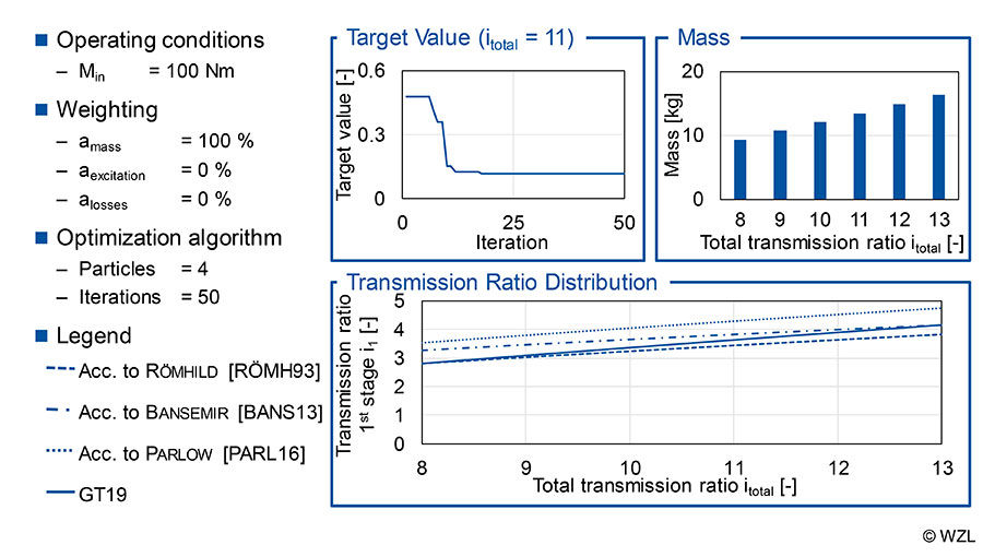
The method developed in the previous chapter is used in the following to design two-stage gearboxes. The focus is, on the one hand, on the mass, and on the other hand, on the dynamic excitation behavior. The range of the total transmission ratio investigated focuses on the usual transmission ratios in e-mobility and extends for both design objectives between 8 ≤ itotal ≤ 13. The drive torque is Min = 100 Nm. In each case, 50 iterations of the particle swarm algorithm are performed with a swarm size of 4 particles.
Verification of the model approach on the basis of the design focus mass. In the investigations on the design focus of the gear mass, only the weighting factor of the mass amass is taken into account and thus further target values are neglected. The course of the target value for the exemplary design of a gearbox with the total transmission ratio itotal = 11 is shown (Fig. 7, top left). The target value aims at the minimum of the target function of Z = 0.116. Up to the 12th iteration, strong improvements in the target value can be observed. From iteration 13 on, only slight reductions can be observed and the target function runs against the target value from iteration 34 on.
In the upper-right part of Figure 7, the resulting masses of the designed gearboxes are listed under consideration of the transmission ratio range. As the transmission ratio increases, the mass also increases from m = 9.4 kg (itotal = 8) to m = 16.4 kg (itotal = 13) due to the assembly space required for the larger gears. The resulting transmission ratio distributions are shown in the bottom part of the figure and are compared with the existing transmission ratio distributions according to Römhild, Bansemir and Parlow (Refs. 29, 19, 13). In general, all courses show similar tendencies with increasing overall transmission ratio, although there are differences due to different boundary conditions. The results of the method developed in this report are sorted between the curves according to Römhild und Bansemir.
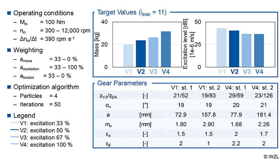
Design focus on dynamic excitation behavior. The analysis of the influence of the dynamic excitation behavior in the design process takes place in a speed range between nin = 300 rpm and nin = 12,000 rpm, with a gradient of the speed ramp of Δnin/Δt = 390 rpms–1. Figure 8 shows the target values of gearbox variants with a total transmission ratio of itotal = 11 and different weighting of the target values; mass and efficiency are always weighted equally. The part of the dynamic excitation behavior is increased consecutively from an equal evaluation of all three target values (V1: aexcitation = 33%) to an exclusive focus on the dynamic excitation behavior (V4: aexcitation = 100%).
The results for the target variables mass and dynamic excitation level are shown in the upper row of Figure 8. With the increasing importance of excitation behavior, the mass increases continuously from V1 (m = 20.2 kg) to V4 (m = 31.7 kg). In contrast, the dynamic excitation behavior of both stages can be reduced by focusing on its reduction from V1 (L = 43.2 dB) to V4 (L = 36.4 dB).
The effect on the gear parameters of variants V1 and V4 is shown in the bottom row of Figure 8. Variant V1, with equally distributed weighting factors, has a transverse contact ratio of ε α = 1.5 and an integer face contact ratio of εβ. Due to the lower torque and the high speed, the first stage has a smaller center distance and a smaller module than the output-side second stage. The pressure angle of αn = 19° represents a compromise with regard to the further target values of efficiency and dynamic excitation behavior. This is also the reason for the ratio of the first stage i1 = 2.48 below the ratio derived in Figure 7 for a minimum mass of i1 = 3.6.
Figure 7: Mass and transmission ratio distribution with design focus mass.
Figure 8: Comparison of target values with design focus dynamic excitation behavior.
Variant V4 differs from variant V1 in terms of the contact ratios and the transmission ratio distribution. Due to the high acoustic weighting, the variant has a high overall contact ratio (εγ,1.stage = 4.2, εγ,2.stage = 3.7). The high contact ratio leads to reduced dynamic excitation behavior. In addition, the transmission ratio distribution results lead to a low ratio (i1 = 2) of the first stage and to a maximum permissible ratio for one stage (i2 = 5.5) for the second stage. The results confirm the tendencies from the work of Brecher et al., in which the annoyance of two-stage gearboxes could be reduced by a very low transmission ratio at the first stage (Ref. 18).
The increase of the mass and the decrease of the dynamic excitation level can mainly be explained by the safety factors. As the weighting of the excitation behavior increases, the safety factors against flank damage increase as well (SH,V1 = 1.4, SH,V4 = 1.7) and lead to higher center distances. In addition, a higher safety factor against tooth root fracture (SF,V1 = 1.9, SF,V4 = 2.2) leads to a higher module. Both factors lead to a higher gear mass and a reduced excitation level.
Brecher et al. developed a two-stage prototype gearbox (Refs. 31, 18) for the investigation of the dynamic noise behavior of two-stage gearboxes. Gears designed for single-stage gearboxes were used and therefore did not take any interactions between the gear stages into account. Various measurement techniques were applied to the test setup to characterize the noise source and the receiver. The difference acceleration (custom-made tangential acceleration measurement systems from datatel Telemetry) was selected as the measurement variable for identifying the excitation source in the gear mesh; the signal was determined for each gear stage separately. The difference velocity corresponds to the integrated difference acceleration and was used for further evaluations due to the good agreement with airborne noise (Ref, 32). The characterization of the noise receiver is represented by the airborne noise recorded by microphones (free field microphones 4189A021 from Brüel Kær).
In the following, a method for the synthesis of airborne noise signals based on calculated simulation results from DynEx1D will be developed and validated on the basis of measurement results. The airborne noise synthesis is then integrated into the design method which has been introduced previously. Based on this, optimized gears with regard to dynamic noise behavior and interactions between the gear stages are designed and compared with the initial variant.
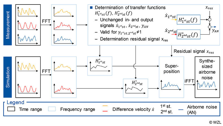
Airborne noise synthesis method. For the analysis of the relationship between gear excitation and emitted airborne noise, a signal theoretical approach according to Bendat was used (Ref. 33). On the one hand, the objective is the mathematical description of the gearbox behavior, as well as the division of the total airborne noise into gear-independent and dependent noise components. With the separated signal components, synthetic airborne noise characteristics can be calculated on the basis of the difference in velocities determined with DynEx1D; the procedure is described in Figure 9.
Figure 9: Airborne noise synthesis method.
Application of the Method to an Existing Gearbox Design
First, the measured difference velocities of both stages and the recorded airborne noise at a microphone are transformed into the frequency domain. The transfer functions H1.st H2.st for a system with two inputs and one output can be determined using signal-theoretical equations. The residual noise χres independent of the gear mesh can be determined by using the inputs and outputs and the determined transfer functions. Difference velocity signals also are the basis for the simulation side. After the transformation into the frequency domain, the transfer functions determined from the experiment are applied to the input signals. The components of the two gear stages are superposed with the remaining signal and transformed back into the time domain.
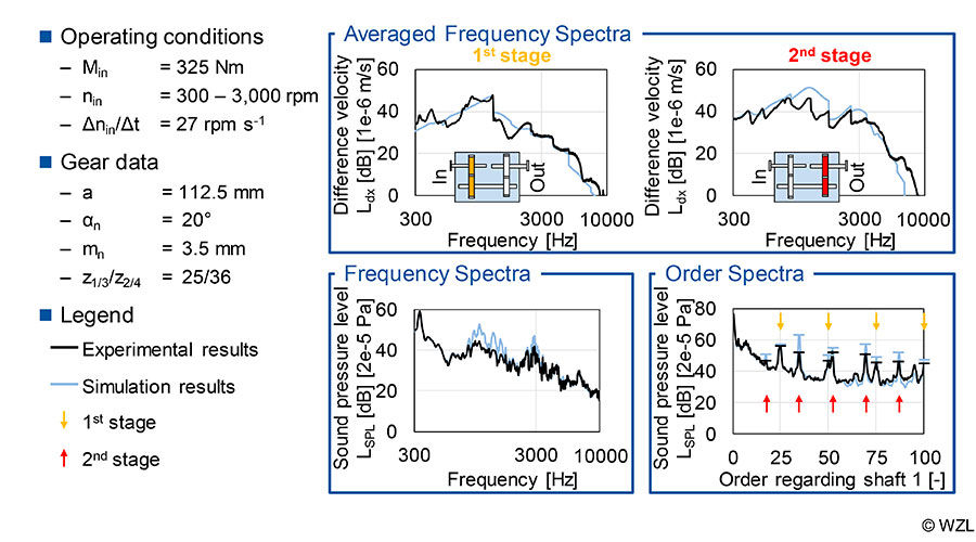
For a comparison between measurement and simulation, the excitation in gear mesh was evaluated using the difference velocity level of the two stages. The results of the calculated and experimental speed run-up are shown (Fig. 10). The left side of the figure shows the results of the drive-side first stage, the right side shows the second stage (output-side). In the psycho-acoustically relevant frequency range between ƒ = 500 Hz and ƒ = 5,000 Hz, high conformity between measurement and simulation can be determined. This is shown, for example, by the peak at ƒ = 1,250 Hz, which dominates the spectrum. Comparing the difference velocities of the second stage measured at the output-side, the characteristic excitation curve is also depicted here by the simulation. Only in the frequency range between ƒ = 1 kHz and ƒ = 1.7 kHz is there a slightly increased excitation in the simulation.
Figure 10: Validation of the method
The method for airborne noise synthesis described in Figure 9 was applied to the simulated difference velocity. The results of the synthesized airborne noise are shown in the lower part of Figure 10, as averaged frequency spectrum and averaged order spectrum. The comparison between simulation and experiment provides a high agreement over the entire frequency range. Only in the frequency range between f = 1–1.7 kHz is the synthesized airborne noise slightly overestimated. This can be explained by the deviations of the difference in velocity of the second stage in the same frequency range. With regard to the order spectrum, a high conformity between measurement and simulation can be determined. Due to the considered residual signal, which is not caused by the gear mesh, the areas between the gear mesh orders are also simulated with the correct level. Similar to the analyses of the difference velocity, the gear mesh orders are slightly overestimated in the simulation.
In summary, for the simulation chain consisting of a multi-body simulation model and airborne noise synthesis, a high consistency for the depiction of excitation and noise behavior can be determined. In the following, the simulation chain can be used to improve the resulting noise behavior.
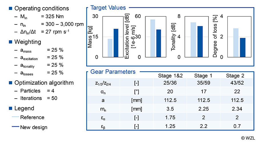
Improvement of an existing gearbox design. In the investigations on the dynamic operational behavior of two-stage gearboxes of Brecher et al., the same gear set was used on both stages (Refs. 30, 18). This reference gear set has a center distance of a = 112.5 mm and a transmission ratio of i = 1.44 (z1/2 = 25/36). Since this gear set was designed for quasi-static, acoustic investigations on single-stage gearboxes, no dynamic interactions between the gear stages were taken into account, thus a new design offers high potential for acoustic improvement.
In order to enable direct comparability with the reference gear set, the center distance a = 112.5 mm is specified as a boundary condition in both stages. Following the investigations of Brecher et al., the same operating conditions are selected (Min = 325 Nm, nin = 300–3,000 rpm, Δnin/Δt = 27 rpms-1) (Refs. 30, 18). As target values the mass, the dynamic excitation behavior, the tonality based on the synthesized airborne noise and the degree of loss are considered — all of which are equally weighted.
The comparison between the reference and the newly designed gearbox is shown (Fig. 11, in the top line) in the top line. This shows that the newly designed variant is only for the target value mass worse than the reference. Considering the other three categories, an improvement can be achieved by the new design. This applies in particular to the target values of dynamic excitation levels and tonality, which include the interactions between the gear stages. The tonality of the new design can be reduced by the coordinated selection of the number of teeth.
Figure 11: Potential of the newly designed variant.
Summary and Outlook
The hybridization and electrification of the drive train have increased the importance of the dynamic excitation and noise behavior of two-stage gearboxes. Consequently, the objective in gear design is to predict the excitation behavior of the gear mesh as accurately as possible at an early design phase by means of frontloading. Due to the high drive speeds present in e-mobility, the dynamic excitation behavior is dominated by the gear mesh frequencies in wide frequency ranges. In gear design, however, quasi-static methods are frequently used which focus on individual stages and neglect interactions between the stages. In addition, the dynamic operational behavior and thus, possible increased excitations by coincidence of excitation and system resonance cannot be considered.
Therefore, the objective of this report is to consider dynamic excitation effects in the gear design of two-stage gearboxes for e-mobility. The first step is to develop a method that combines macrogeometric gear design with the simulation of dynamic excitation behavior. The DynEx1D simulation software is used to evaluate the dynamic excitation behavior. A particle swarm algorithm is used to reduce the computing time. The evaluation of the variants is based on different target values with focus on the dynamic excitation level.
The method is then used to design gearboxes for e-mobility. For this purpose, a transmission ratio range between 8 ≤ itotal ≤ 13 and a drive speed up to nin = 12,000 rpm is investigated. With a focus on the target value mass, comparable recommendations known from the literature can be made for the transmission ratio distribution. With a focus on the dynamic excitation behavior, an improvement and thus a reduction of the gear excitation leads to an increase in the drive mass. Furthermore, the ratio of the first stage i1 decreases with the increasing importance of excitation behavior. In order to consider the tonality of an existing gearbox, the method is extended by airborne noise synthesis using an experimentally determined transfer function. The newly designed variant shows the acoustic potential in which tonality and dynamic excitation level could be reduced.
In the future, further target values are to be considered in the design process that focus on the dynamic interactions between the stages. Axial force vibrations can be reduced by a targeted design of the axial forces at the intermediate shaft. Finally, the consonance and dissonance effects known from music theory can be transferred to two-stage gearboxes.
Acknowledgement. The authors gratefully acknowledge financial support by the German Research Foundation (DFG) [BR 2905/66-1] for the achievement of the project results. The authors gratefully acknowledge financial support by the WZL Gear Research Circle for the development of the dynamic multi-body simulation software DynEx1D.
For more Information
Questions or comments regarding this paper?
Contact Marius Schroers at m.schroers@wzl.rwth-aachen.de.
 Marius Schroers, M.Sc., studied mechanical engineering at RWTH Aachen University until 2015. Since then, he has been working as a research assistant, first in the group “Gear Design and Manufacturing Simulation,” and since 2019 in the newly founded group “Gear Acoustics” in the Gear Department of the Laboratory of Machine Tools and Production Engineering (WZL). His research activities focus on the dynamic behavior of multi-stage gearboxes and the correlation between excitation, noise radiation and the perception-related evaluation of gearbox noise.
 Prof. Dr.-Ing. Christian Brecher has since January 2004 been Ordinary Professor for Machine Tools at the Laboratory for Machine Tools and Production Engineering (WZL) of the RWTH Aachen, as well as Director of the Department for Production Machines at the Fraunhofer Institute for Production Technology IPT. Upon finishing his academic studies in mechanical engineering, Brecher started his professional career first as a research assistant and later as team leader in the department for machine investigation and evaluation at the WZL. From 1999 to April 2001, he was responsible for the department of machine tools in his capacity as a Senior Engineer. After a short spell as a consultant in the aviation industry, Professor Brecher was appointed in August 2001 as the Director for Development at the DS Technologie Werkzeugmaschinenbau GmbH, Mönchengladbach, where he was responsible for construction and development until December 2003. Brecher has received numerous honors and awards, including the Springorum Commemorative Coin; the Borchers Medal of the RWTH Aachen; the Scholarship Award of the Association of German Tool Manufacturers (Verein Deutscher Werkzeugmaschinenfabriken VDW); and the Otto Kienzle Memorial Coin of the Scientific Society for Production Technology (Wissenschaftliche Gesellschaft für Produktionstechnik WGP).
 Dr. -Ing. Dipl. -Wirt. -Ing. Christoph Löpenhaus is working as Business Development Manager at Cerobear GmbH, Herzogenrath, Germany, since 2019. From 2014 to 2019, he served as Chief Engineer in the Gear Department of Laboratory for Machine Tools and Production Engineering WZL of RWTH Aachen.
References
- Norm AGMA 2001-D04 (Dezember 2004) Fundamental Rating Factors and Calculation Methods for Involute Spur and Helical Gear Teeth.
- Bansemir, G.: Konstruktionsleitsystem für den durchgängig rechnerbasierten Zahnradgetriebeentwurf.Diss. TU München, 2013.
- Bendat, J.; Piersol, A.: Random data. Analysis and measurement procedures. 4. ed. Hoboken, NJ: Wiley, 2010.
- Brecher, C.; Löpenhaus, C.; Schroers, M.: Analysis of dynamic excitation behavior of a two-stage spur gearbox. In: Proc. CIRP, Vol. 62, 2017, pp. 369–374.
- Brecher, C.; Schroers, M.; Löpenhaus, C.: Experimental analysis of the dynamic noise behavior of a two-stage cylindrical gearbox. In: Prod. Eng. Res. Devel., Vol. 11, 2017, No. 6, pp. 695–702.
- Brecher, C.: FE-Stirnradkette v4.2.19. Benutzeranleitung zum Programm, Forschungsvereinigung Antriebstechnik e.V., Frankfurt a.M., 2017.
- Brecher, C.; Löpenhaus, C.; Schroers, M.: Influence of the number of teeth on the dynamic excitation behavior of two-stage cylindrical gearboxes International Gear Conference. Lyon, 27.-29.08.2018. Oxford: Chartridge Books, 2018.
- Carl, C.: Gehörbezogene Analyse und Synthese der vibroakustischen Geräuschanregung von Verzahnungen. Diss. RWTH Aachen University, 2014.
- Craig Jr., R.; Bampton, M.: Coupling of Substructures for Dynamic Analyses. In: AIAA J., Vol. 6, 1968, No. 7, pp. 1313–1319.
- Norm DIN 3990 Teil 2 (Dezember 1987) Tragfähigkeitsberechnung von Stirnrädern Teil 2. Berechnung der Grübchentragfähigkeit.
- Norm DIN 3990 Teil 1 (Dezember 1987) Tragfähigkeitsberechnung von Stirnrädern Teil 1. Einführung und allgemeine Einflußfaktoren.
- Norm DIN 45681 (März 2005) Akustik. Bestimmung der Tonhaltigkeit von Geräuschen und Ermittlung eines Tonzuschlages für die Beurteilung von Geräuschimmissionen.
- Ehrlenspiel, K.; Figel, K.: Kostengünstige Übersetzungsaufteilung bei mehrstufigen Stirnradgetrieben. In: antriebstechnik, 1985, No. 24, pp. 51–54.
- Fingerhuth, S.: Tonalness and consonance of technical sounds. Diss. RWTH Aachen University, 2009.
- Gacka, A.: Entwicklung einer Methode zur Abbildung der dynamischen Zahneingriffsverhältnisse von Stirnund Kegelradsätzen. Diss. RWTH Aachen University, 2013.
- Gerber, H.: Innere dynamische Zusatzkräfte bei Stirnradgetrieben. Modellbildung, Innere Anregung und Dämpfung. Diss. TU München, 1984.
- GKN Into the mainstream. www.gknepowertrain.com/en/solutions/case-studies/2016/bmw-2se-ries/ [state: 20.03.2019].
- Norm ISO 6336 Teil 2 (September 2006) Calculation of load capacity of spur and helical gears. Calculation of surface durability (pitting).
- Norm ISO 6336 Teil 1 (September 2006) Calculation of load capacity of spur and helical gears. Basic principles, introduction and general influence factors.
- Jaroš, M.: Integration des STEP-Produktmodells in den etriebeentwicklungsprozess. Diss. TU München, 2006.
- Klemenz, M.: Die Geräuschqualität bei der Anfahrt elektrischer Schienenfahrzeuge. Diss. RWTH Aachen University, 2005.
- Klocke, F.; Brecher, C.: Zahnradund Getriebetechnik. Auslegung -Herstellung -Untersuchung -Simulation. 1. ed. München: Carl Hanser, 2017.
- Kubur, M.; Kahraman, A.; Zini, D.; Kienzle, K.: Dynamic Analysis of a Multi-Shaft Helical Gear Transmission by Finite Elements. Model and Experiment. In: J. Vib. Acoust., Vol. 126, 2004, No. 3, pp. 398–406.
- Linke, H.: Stirnradverzahnung. Berechnung -Werkstoffe -Fertigung. 2. ed. München: Hanser, 2010.
- Möser, H.: Übersetzungsaufteilung bei mehrstufigen Getrieben. In: Maschinenbautechnik, 1982, No. 31, pp. 171–173.
- Müller, R.: Schwingungsund Geräuschanregung bei Stirnradgetrieben. Diss. TU München, 1991.
- Naunheimer, H.; Bertsche, B.; Lechner, G.; Ryborz, J.; Novak, W.: Fahrzeuggetriebe. Grundlagen, Auswahl, Auslegung und Konstruktion. 2. ed. Berlin: Springer, 2007.
- Niemann, G.; Winter, H.: Maschinenelemente. Band 2: Getriebe allgemein, Zahnradgetriebe -Grundlagen, Stirnradgetriebe. Vol. 2, 2. ed. Berlin: Springer, 2003.
- Parlow, J.: Entwicklung einer Methode zum anforderungsgerechten Entwurf von Stirnradgetrieben. Diss. TU München, 2016.
- Perez, R.; Behdinan, K.: Particle swarm approach for structural design optimization. In: Comp. Struc. (Computers & Structures), Vol. 85, 2007, No. 19–20, pp. 1579–1588.
- Römhild, I.: Auslegung mehrstufiger Stirnradgetriebe-Übersetzungsaufteilung für minimale Masse und Wahl der Profilverschiebung auf der Basis neuer Berechnungsgrundlagen. Diss. TU Dresden, 1993.
- Savsani, V.; Rao, R.V.; Vakharia, D.: Optimal weight design of a gear train using particle swarm optimization and simulated annealing algorithms. In: Mech. Mach. Theo., 2010, No. 45, pp. 531–541.
-
Schlenk, L.: Untersuchungen zur Fresstragfähigkeit von Großzahnrädern. Diss. TU München, 1995.
- Yokota, T.; Taguchi, T., Gen, M: A solution method for optimal weight design problem of the gear using genetic algorithms. In: Computers & Industrial Engineering, 1998, No. 35, pp. 523–526.