Explosion-Proof Motors in Division 2 Areas and DC Drive Fundamentals
Edward Cowern, P.E.
We have found that one of the most confusing
things about explosion-proof requirements involves the application of motors in
Division 2 areas. To put things in perspective, Division 1 involves areas where
hazardous liquids, vapors, gases or hazardous dusts are present a good deal of
the time, or even all the time, in the normal course of events.
Division 2 areas are where the hazardous materials are
only apt to be in the area if there is a spill, accident, loss of ventilation
or some other unusual condition; the treatment of both of these divisions is
covered in Article 500 of the National Electric Code (NEC).
Once an area has been identified as being either Division
1 or Division 2, the NEC requires certain types of motors be used in those
environments. Division 1 areas always require hazardous location
(explosion-proof) motors having the class and group approvals that match the
particular hazardous substance in the area. Thus, for Division 1 requirements
explosion-proof equipment must be used. On the other hand, if an area has been
classified as Division 2, the National Electric Code will frequently allow the
use of totally enclosed (or even open drip-proof) motors, provided certain
conditions are met. Basically, those conditions relate to there not being any
hot surfaces or sparking parts in the motor. For example, sparking parts could
be brushes (as found in DC motors), switching devices (such as centrifugal
switches used in many single-phase motors), thermostats or thermal overloads
normally found in thermally protected motors, or space heaters that might have
high surface temperatures.
In essence, what the code is saying is that three-phase
induction motors that do not have high- temperature surfaces or sparking parts
will not, in normal operation, be likely to ignite the surrounding environment.
They can be used because the likelihood of a (spark-producing) failure of the
motor occurring at the same time that a spill or accident occurs is so remote
it is a very unlikely event.
One way to avoid conflicts on interpretations of what is
needed is to “play safe” and use hazardous location motors for both Division 1
and Division 2 requirements. This is a safe but expensive option, and becomes
more expensive as motors get larger.
A second choice is to use three-phase TEFC or even open
drip-proof motors that meet the non-sparking and no-hot-surfaces requirements
for Division 2.
For machinery builders or contractors who want to use the
less expensive motors for Division 2 requirements, it is always wise to make
your intentions known to the customer in advance. Perhaps the best way to do
this would be to notify them by letter, with a statement such as follows:
“Since your stated requirement is Class (fill in
appropriate references), Group (fill inappropriate references),
Division 2, it is our intention to supply totally enclosed, fan-cooled,
three-phase induction motors in accordance with paragraph (1) of the National
Electric Code. If you object to this, please notify us as soon as possible.”
By using this type of letter to make your intentions
clear, it is much less likely that a dispute over interpretation will develop
at a later time.
If you should have any questions regarding this
requirement, please refer to the NEC for the appropriate section based on the
class, group and division of the requirement.
(1) Paragraph references
For Class I..........501-8(b)
For Class II..........502-8(b)
When using motors in Division-2 areas with an inverter
power supply, refer to comments in the February 2018 issue of Power
Transmission Engineering (How to Select Motors for Hazardous Locations, pages 46–47.)
DC Drive Fundamentals
[advertisement]
Understanding DC drives. DC motors
have been available for nearly 100 years. In fact, the first electric motors
were designed and built for operation from direct current (DC) power.
Alternating current (AC) motors are now, and will of course remain, the basic
prime movers for the fixed speed requirements of industry. Their basic
simplicity, dependability and ruggedness make AC motors the natural choice for
the vast majority of industrial drive applications.
Then where do DC drives fit into the industrial drive
picture of the future?
In order to supply the answer, it is necessary to examine
some of the basic characteristics obtainable from DC motors and their
associated solid-state controls.
1. Wide speed range
2. Good speed regulation
3. Compact size and lightweight (relative to mechanical
variable speed)
4. Ease of control
5. Low maintenance
6. Low cost
In order to realize how a DC drive has the capability to
provide the above characteristics, the DC drive has to be analyzed as two
elements that make up the package. These two elements are of course the motor
and the control. (The “control” is more accurately called the “regulator.”)
DC motors. Basic
DC motors, as used on nearly all packaged drives, have a very simple
performance characteristic—the shaft turns at a speed almost directly
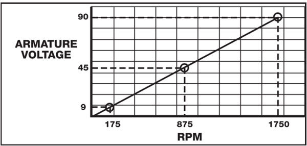
proportional to the voltage applied to the armature. Figure 1 shows a typical
voltage/speed curve for a motor operating from a 115-volt control.
Figure 1—Typical voltage/speed curve for motor operating from 115 volt control.
From the above curve you can see that with 9 volts applied
to the armature, this motor would be operating at Point 1 and turn at approximately
1,75 RPM. Similarly, with 45 volts applied the motor would be operating at
Point 2 on the curve, or 875 RPM. With 90 volts applied, the motor would reach
its full speed of 1,750 RPM at Point 3.
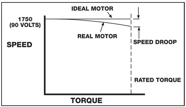
From this example a general statement can be made that DC
motors have “no load” characteristics that are nearly a perfect match for the
curve indicated in Figure 1. However, when operated at a fixed applied voltage,
and with a gradually increasing torque load, they exhibit a speed droop (Fig.2).
Figure 2—When operated at a fixed, applied voltage with a gradually increasing torque load, DC motors
exhibit a speed droop.
This speed droop is very similar to what would occur if an
automobile’s accelerator pedal was held in a fixed position with the car
running on level ground. Upon starting up an incline, where more driving torque
would be needed, the car would slow down to a speed related to the steepness of
the hill. In a real situation, the driver would respond by depressing the
accelerator pedal to compensate for the speed loss to maintain a nearly
constant speed up the incline.
In the DC drive a similar type of “compensation” is
employed in the control to assist in maintaining a nearly constant speed under
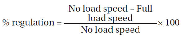
varying load (torque) conditions. The measurement of this tendency to slow down
is called “regulation” and is calculated with the following equation:
In DC drives the regulation is generally expressed as a
percentage of motor base speed.
If the control (regulator) did not have the
capability of responding to and compensating for changing motor loads,
regulation of typical motors might be as shown in Table 1.
Table 1 DC drive regulation is generally expressed
as a percentage of motor base speed;
if control (regulator) lacks capability of
responding to and compensating for
changing motor loads, regulation of
typical motors might be as shown in
Table 1.
HP
% MOTOR REGULATION
¼
13.6
1/3
12.9
½
13.3
¾
10.8
1
6.7
1½
8.0
2
7.2
3
4.2
5
2.9
7½
2.3
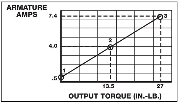
One other very important characteristic of a DC motor
should be noted. Armature amperage is almost directly proportional to output
torque—regardless of
speed; this characteristic is shown in Figure 3. Point 1 indicates that a
small, fixed amount of current is required to turn the motor, even when there
is no output torque. This is due to the friction of the bearings, electrical
losses in the motor materials, and load imposed by the air in the motor
(windage).
Beyond Point 1 through Point 2 and 3, the current
increases in direct proportion to the torque required by the load.
From this discussion and Figure 3, a general statement can
be made that for PM and shunt wound motors, load torque determines armature
amperage.
Figure 3—Beyond Point 1 and through Points 2 and 3, the current increases in direct proportion to the
torque
In summary, two general statements can be made relative to
DC motor performance.
1. Motor speed is primarily determined by applied
armature voltage
2. Motor torque is controlled by armature
current (amperes)
Understanding these two concepts of DC motors provides the
key to understanding total drive performance.
Regulators (controls). The control provides
two basic functions:
1. It rectifies AC power, converting it to DC
for the DC motor.
2. It controls the DC output voltage and
amperage in response to various control and feedback signals, thereby
regulating the motor’s performance, both in speed and torque.
Rectifying function. The basic rectifying
function of the control is accomplished by a combination of power
semiconductors (silicon-controlled rectifiers and diodes) that make up the
“power bridge” assembly.
Regulating function. The regulating function
is provided by a relatively simple electronic circuit that monitors a number of
inputs and sums these signals to produce a so called “error signal.” This error
signal is processed and transformed into precisely timed pulses (bursts of
electrical energy). These pulses are applied to the gates of the SCRs in the power
bridge, thereby regulating the power output to the DC motor.
For most purposes it is not necessary to understand the
electronic details of the regulator; however, in order to appreciate the
regulator function it is good to understand some of the input signals that are
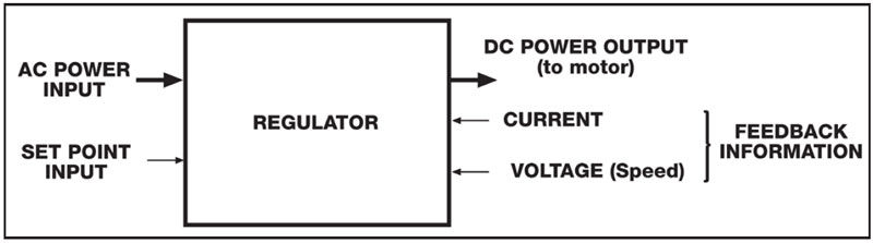
required to give the regulator its capabilities (Fig.4).
Figure 4—Input signals required to give regulator its capabilities.
The AC-to-DC power flow is a relatively simple, straight
through process with the power being converted from AC to DC by the action of
the solid-state power devices that form the power bridge assembly.
The input and feedback signals need to be studied in more
detail.
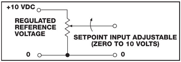
Set point input. In most packaged drives
this signal is derived from a closely regulated, fixed- voltage source applied
to a potentiometer; 10 volts is a very common reference.
The potentiometer has the capability of accepting the
fixed voltage and dividing it down to any value from, for example, 10 to zero
volts—depending on where
it is set. A 10-volt input to the regulator from the speed adjustment control
(potentiometer) corresponds to maximum motor speed; zero volts correspond to
zero speed. Similarly, any speed between zero and maximum can be obtained by
adjusting the speed control to the appropriate setting.
Speed feedback information. In order to
“close the loop” and control motor speed accurately, it is necessary to provide
the control with a feedback signal related to motor speed.
The standard method of doing this in a simple control is
by monitoring the armature voltage and feeding it back into the regulator for
comparison with the input “set point” signal.
When armature voltage becomes high, relative to the set point
and established by the speed potentiometer setting, an “error” is detected and
the output voltage from the power bridge is reduced to lower the motor’s speed
back to the “set point.” Similarly, when the armature voltage drops, an error
of opposite polarity is sensed and the control output voltage is automatically
increased in an attempt to re-establish the desired speed.
Figure 5—Set point input signal derived from foxed voltage source.
The “armature voltage feedback system,” which is standard
in most packaged drives, is generally called a “voltage-regulated drive.”
A second and more accurate method of obtaining the motor
speed feedback information is called “tachometer feedback.” In this case the
speed feedback signal is obtained from a motor-mounted tachometer; the output
of this tachometer is directly related to the speed of the motor. Using
tachometer feedback generally gives a drive improved regulation
characteristics. When “tach feedback” is used, the drive is referred to as a
“speed-regulated drive.” Most controls are capable of being modified to accept
tachometer signals for operation in the tachometer feedback mode.
In some newer, high-performance “digital drives” the
feedback can come from a motor-mounted encoder that feeds back voltage pulses
at a rate related to motor speed. These (counts) are processed digitally, being
compared to the “set point,” and error signals are produced to regulate the
armature voltage and speed.
Current feedback. The second source of
feedback information is obtained by monitoring the motor armature current. As
discussed previously, this is an accurate indication of the torque required by
the load.
The current feedback signal is used for two purposes:
1. As positive feedback to eliminate the speed
droop that occurs with increased torque load on the motor. It accomplishes this
by making a slight corrective increase in armature voltage as the armature
current increases.
2. Asnegative feedback with a
“threshold-type” of control that limits the current to a value that will
protect the power semiconductors from damage. By making this function
adjustable, it can be used to control the maximum torque the motor can deliver
to the load.
The current limiting action of most controls is adjustable
and is usually called “current limit” or “torque limit.”
In summary, the regulator accomplishes two basic
functions:
1. It converts the alternating current to direct
current
2. It regulates the armature voltage and current to
control the speed and torque of the DC motor
Typical Adjustments
In addition to the normal external adjustment,
such as the speed potentiometer, there are a number of common, internal adjustments
that are used on simple, small analog-type SCR drives. Some of these
adjustments are:
Minimum speed
Maximum speed
Current limit (torque limit)
IR compensation
Acceleration time
Deceleration time
The following is a description of the function that these
individual adjustments serve, and their typical use.
Minimum speed. In most cases, when the
control is initially installed the speed potentiometer can be turned down to
its lowest point and the output voltage from the control will go to zero,
causing the motor to stop. There are many situations where this is not
desirable. For example, there are some machines that want to be kept running at
a minimum speed and accelerated up to operating speed as necessary. There is
also a possibility that an operator may use the speed potentiometer to stop the
motor to work on the machine.
This can be a dangerous situation, since the motor has
only been brought to a stop by zeroing the input signal voltage. A more
desirable situation is when the motor is stopped by opening the circuit to the
motor or power to the control using the on/off switch. By adjusting the minimum
speed up to some point where the motor continues to run—even
with the speed potentiometer set to its lowest point—the
operator must shut the control off to stop the motor. This adds a degree of
safety into the system. The typical minimum speed adjustment is from 0 to 30%
of motor base speed.
Maximum speed. The maximum speed adjustment
sets the maximum speed attainable either by raising the input signal to its
maximum point or turning the potentiometer to the maximum point. For example,
on a typical DC motor the rated speed of the motor might be 1,750 RPM, but the
control might be capable of running it up to 1,850 or 1,900 RPM. In some cases
it is desirable to limit the motor (and machine speed) to something less than
would be available at this maximum setting; the maximum adjustment allows this
to be done. By turning the internal potentiometer to a lower point, the maximum
output voltage from the control is limited. This limits the maximum speed
available from the motor. In typical controls such as Baldor’s BC140, the range
of adjustment on the maximum speed is from 50 to 110% of motor base speed.
Current limit. One very nice feature of
electronic speed controls is that the current going to the motor is constantly
monitored by the control. As mentioned previously, the current drawn by the
armature of the DC motor is related to the torque that is required by the load.
Since this monitoring and control is available, an adjustment is provided in
the control that limits the output current to a maximum value.
This function can be used to set a threshold point that
will cause the motor to stall rather than putting out an excessive amount of
torque. This capability gives the motor/control combination the ability to
prevent damage that might otherwise occur if higher values of torque were
available. This is handy on machines that might become jammed or otherwise
stalled. It can also be used where the control is operating a device such as
the center winder, where the important thing becomes torque rather than
speed. In this case the current limit is set and the speed goes up or down to
hold the tension of the material being wound. The current limit is normally
factory-set at 150% of the motor’s rated current. This allows the motor to
produce enough torque to start and accelerate the load, and yet will not let
the current (and torque) exceed 150% of its rated value when running. The range
of adjustment is typically from 0 to 200% of the motor-rated current.
IR compensation. IR compensation is a method
used to adjust for the droop in a motor’s speed due to armature resistance. As
mentioned previously, IR compensation is positive feedback that causes the
control output voltage to rise slightly with increasing output current. This
will help stabilize the motor’s speed from a no-load to full-load condition. If
the motor happens to be driving a load where the torque is constant or nearly
so, then this adjustment is usually unnecessary. However, if the motor is
driving a load with a widely fluctuating torque requirement, and speed
regulation is critical, then IR compensation can be adjusted to stabilize the
speed from the light load to full load condition. One caution is that when IR
compensation is adjusted too high, it results in an increasing speed
characteristic. This means that as the load is applied, the motor is actually
going to be forced to run faster. When this happens it increases the voltage
and current to the motor that, in turn, increases the motor speed further. If
this adjustment is set too high, an unstable “hunting” or oscillating condition
occurs that is undesirable.
Acceleration time. The acceleration time
adjustment performs the function that is indicated by its name. It will extend
or shorten the amount of time for the motor to go from zero speed up to the set
speed. It also regulates the time it takes to change speeds from one setting
(say 50%) to another setting (perhaps 100%). So this setting has the ability to
moderate the acceleration rate on the drive.
A couple notes are important: if an acceleration
time that is too rapid is called for, “acceleration time” will be overridden by
the current limit. Acceleration will only occur at a rate that is allowed by
the amount of current the control passes through to the motor. Also important
to note is that on most small controls the acceleration time is not linear,
meaning that a change of 50 RPM may occur more rapidly when the motor is at low
speed than it does when the motor is approaching the set point speed. This is
important to know but usually not critical on simple applications where these
drives are used.
Deceleration time. This is an adjustment
that allows loads to be slowed over an extended period of time. For example, if
power is removed from the motor and the load stops in 3 seconds, then the
“decel” time adjustment would allow you to increase that time and “power down”
the load over a period of 4, 5, 6 or more seconds. Note: On a conventional,
simple DC drive it will not allow for the shortening of the time below the
“coast to rest” time.
Adjustment summary. The ability to make
these six adjustments affords great flexibility to the typical, inexpensive DC
drive. In most cases the factory-preset settings are adequate and need not be
changed; but on other applications it may be desirable to tailor the
characteristics of the control to the specific application.
Many of these adjustments are available in other types of
controls, such as variable frequency drives (VFDs).