Losses are generated on the effective contact of two surfaces when these move with respect to each other, and they are inherent not just in solid bodies’ contact but also in fluids and gasses. The function of a gearbox is the transfer of mechanical power, which involves multiple of these body contacts between its gearwheels, bearings, lubricant, air, sealings, etc.
For a robotic gearbox, losses are detrimental because they contribute to a faster depletion of the battery and thus either larger (e.g., heavier) batteries or the need for frequent charging, both nondesirable options for a collaborative device. Further, low efficiency means that a fraction of the power input in the gearbox cannot be converted into output torque, and thus, a larger motor is required to cope with the robot’s task.
A popular classification of losses in gearboxes distinguishes first between load-independent (or no-load) and load-dependent losses, assuming that these are not coupled (Ref. 14). No-load losses refer to the gearbox losses when no external load is applied to the gearbox and originate from sliding and rolling friction on the elastohydrodynamic (EHD) contact between the gear teeth (typically neglected in unloaded conditions) in mesh and the bearing contacts (mainly drag losses), as well as through lubricant churning inside the gearbox, lubricant pocketing between the gear teeth, and friction with the sealings. On the other side, load-dependent losses originate from contact forces and relative sliding and are frequently analyzed following a Coulomb friction model (Ref. 15).
This separation between no-load and load-dependent losses is instrumental in evaluating a gearbox’s suitability for robotic operations (Ref. 1). Robot operations tend to involve frequent changes between low-torque and moderately-high-speed conditions, where no-load losses are decisive, and high-torque with low-speed conditions, where the load-dependent losses are then determinant (Ref. 16). The result of this situation is that, almost systematically, the effective efficiency of a robotic gearbox when subject to typical robotic-operation conditions falls well below 50 percent, even when the gearbox peak efficiency that the manufacturers reflect in the datasheet is often close to 85 percent (Ref. 5).
Our assessment framework incorporates thus one parameter to reflect the effect of the no-load losses (starting torque) and two other parameters to reflect the load-dependent losses (peak efficiency and latent-power ratio [LPR]). Starting torque indicates the torque that needs to be applied to a gearbox’s input shaft to initiate movement on its output shaft under unloaded conditions, thus providing a good characterization of its no-load losses. On the other side, our research indicates that the load-dependent losses are mainly driven by the gear teeth’ meshing efficiency and gearbox topology. Indeed, the sliding mechanism under which losses are primarily generated in gear tooth contact is susceptible to the gearwheels’ normal forces and relative speeds. In most robotic gearboxes, their internal configuration results in composed rotational movements and relative gearwheel speeds that are an order of magnitude larger than for an inertial system, in which the gear shafts are connected to a fixed housing through bearings. These composed rotational movements lead to substantial losses in the gear meshings. Chen (Ref. 17) introduced a latent power concept that we apply in our LPR ratio to characterize this phenomenon. The LPR for a meshing (j) is calculated by multiplying the torque input (xj) in the meshing (j) and the speed input in this meshing, seen from a non-inertial observed moving with the gearbox carrier (C) at a speed (𝜔j-𝜔C). Dividing this by the input power to the gearbox (PIn) we obtain the LPR of meshing (j) as 𝜆j:

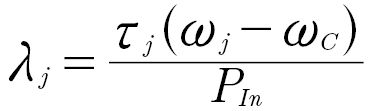 (1)
(1)
The meshing losses on each meshing can now be estimated using Ohlendorf’s Equation 2 to relate the power losses (Lj) on that meshing to its LPR ( 𝜆j), the input power to the gearbox (PIn), a friction coefficient between the meshing’s teeth surfaces averaged through the complete contact line-of-action (𝜇m,j), and a meshing loss factor (Hv,j) that depends on the macrogeometry parameters of the gear teeth of the gears involved in that meshing:

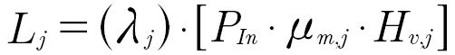 (2)
(2)

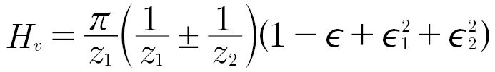 (3)
(3)
where
Zk is the number of teeth of gear "k"
𝜖 is the meshing's contact ratio
𝜖1 is the approach contact ratio
𝜖2 is the recess contact ratio
For a reference meshing in which the gear shafts are rigidly connected to a fixed housing through bearings (thus ~C=0), the losses (Lref) are instead:

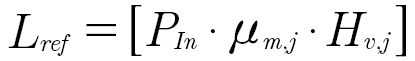 (4)
(4)
And we can write that:

 (5)
(5)
Equation 5 shows that the LPR can be interpreted as a multiplication factor of the meshing (load-dependent) losses that these meshing would see in a conventional parallel shafts gearbox in which the housing is rigidly fixed, and all gear shafts are connected to this housing directly through bearings. Adding the LPRs of all meshing in a gearbox, we obtain a reasonable estimation of the amplification factor of the gearbox’s topology on the meshing losses, which provides a valuable and complementary perspective on the load-dependent losses to the peak efficiency value from the catalog.
Actuator’s Backdrivability
Backdrivability indicates an actuator’s mechanical compliance to be driven from the load side. As the mechanical compliance (Ci) relates angular displacement (a) to torque (x), it can easily be confirmed that, assuming in the first instance no losses, adding a gearbox with a gear ratio (iG) increases the effective mechanical compliance of the load seen from the motor (mot)—thus reflected to the motor side, or forward (Fwd) compliance—multiplied by the factor (iG2), while at the same time, the compliance of the motor seen this time from the load (L)—thus reflected to the load side, or backward (Bck) compliance—is reduced, multiplied by the factor (1⁄iG2):
 (6)
(6)
 seen from the motor (Forward Compliance) (7)
 seen from the load (Backward Compliance) (8)
According to the above definition, an actuator’s backdrivability will be determined by its backward compliance, thus by the mechanical compliance of the motor’s rotor, including its three components, stiffness, inertia, and damping—divided by the square of the gearbox’s reduction ratio. In reality, the gearbox’s compliance also has a specific contribution to the overall actuator’s backward compliance. For stiffness and inertia, the effect of the square of the reduction ratios makes the motor’s rotor the dominant contributor to the actuator’s reflected inertia and stiffness by a large margin (Ref. 18). For damping, gearboxes tend to have substantially larger losses than the few bearings’ mechanical losses of the motor’s rotor, such that the effect of friction in the gearbox should actually be accounted for when evaluating backdrivability.
Typically, motor rotors, gearbox gears, and shafts are manufactured in high-strength steel with very large stiffnesses such that their contribution to the backdriving compliance—particularly after reflecting them to the load side—can be neglected. Thus, for rigid enough actuators, backdriving is typically governed by the combined effect of damping (friction) in the gearbox and motor and by the inertia of the motor’s rotor.
In principle, this analysis correlates acceptably well with the general understanding in the robotics community that high gear ratios result in very high rotor inertias when reflected to the load side, due to the effect of the square of the gear ratio, making these actuators practically non-backdrivable. This reasoning underlies the recent interest of this community in direct-drive (DD) and quasi-direct drive (QDD) actuators, which try to minimize gear ratio to enable better backdriving properties. Prominent examples of this strategy are given by Ref. 6 and Ref. 19. But, in our experience (Ref. 20), there are some fundamental flaws in this strategy: first and foremost, even if the recent development of high-torque electrical motors has improved their torque density, the torque densities of DD and QDD actuators are significantly lower than what is possible using high ratio gearboxes, and we have seen in “Reduction Ratio and Torque Density” how relevant this aspect is for a robotic gearbox. Secondly, high-torque motors tend to have substantially larger rotor inertias, such that, in the end, the gain in reflected inertia that results from reducing the reduction ratio is surprisingly limited. And finally, when the backdriving accelerations are not very large—as is commonly the case in collaborative robotics—it is actually damping—mainly gearbox friction—and not inertia that plays the dominant role in backward compliance.
The results obtained by Matsuki et al. (Ref. 21) and Lopez et al. (Ref. 18) testing backdrivability in prototypes of Wolfrom-based gearboxes with substantially improved efficiency correlate well with this hypothesis.
To characterize the backdrivability of a gearbox, our assessment framework, therefore, uses the parameter backdriving torque, which is usually provided by the manufacturer in the gearbox’s datasheet.
Gearbox Hysteresis and Transmission Error
Current robotic gearboxes have been engineered to match the demanding accuracy needs of conventional industrial robots. Positioning and repeatability accuracies in the range of ±20 μm are not unusual for industrial robots with six to seven joints and total arm lengths close to two meters. In the structured and highly predictable environment in which these robots operate, positioning accuracy is the key to success.
Collaborative devices must cope with the uncertainties of human environments like our homes and offices, in which the position of objects is not precisely known and where humans, animals, etc., can emerge from nowhere in almost no time. A strategy based on extreme positioning accuracy is thus not a practical solution. Most collaborative devices are actually well-served with ten to twenty times smaller positioning accuracy than those typical in industrial robots. Collaborative robots use advanced sensing and force-control techniques to more effectively adapt to their less predictable and quite unstructured environments.
There exists thus a fundamental paradigm change in terms of positioning accuracy between conventional industrial robots and collaborative robots. As this change of needs is narrowly related to the movement capabilities of a robot, it is directly mirrored in the accuracy needs of the gearboxes used in its joints.
In our assessment framework, we have chosen to use two parameters—hysteresis and transmission error—to characterize the accuracy of a gearbox. Gearbox hysteresis is a statically determined curve with a loop shape that results from representing the angular displacement of the gearbox output versus the output torque, with fixed gearbox input, during a loading cycle in one rotational direction until nominal torque, immediately followed by unloading, and then repeating the process in the other rotational direction. This curve is particularly useful for a number of reasons:
- The surface between the loading and unloading curves corresponds to the gearbox’s efficiency.
- The lost motion (or position error), which integrates the effects of torsional stiffness and backlash behavior, indicates how much the gearbox output can rotate with a blocked gearbox input and can be directly determined from the hysteresis curve as the difference between the maximum and minimum angular displacements of the gearbox output at zero torque.
- The deviation of these curves from a straight line indicates a nonconstant gearbox stiffness that changes under load as a result of internal torsion, deformations—for example, in the gear teeth—and flattening due to high Hertzian stresses. It is particularly relevant for the gearbox’s dynamics.
When the hysteresis curves are not available from the manufacturer, lost motion and stiffness variation can be used as alternative parameters to assess the hysteresis of the gearbox.
The transmission error is a dynamically determined error that indicates the deviation percentage of output angular speed with respect to the theoretical output speed, calculated by dividing the input angular speed by the reduction ratio. This parameter describes the accuracy of a transfer function between the movement of the gearbox’s input and output. It is critical for accuracy and results from the interaction of concentricity and other assembly errors with indexing errors, tooth corrections, stiffness variations during meshing, and other geometrical deviations.
Manufacturing Complexity
Collaborative robotics has the potential to extend robotics beyond manufacturing areas and mass production into our homes, offices, and other areas where more customized services and products are provided or manufactured. Good affordability is a highly desirable property often limited by the traditionally high cost of robotic gearboxes to materialize this potential. For a cobot with six or seven degrees of freedom—thus six or seven joints and actuators—the high cost of its gearboxes often represents an unsurmountable obstacle for broader adoption.
Although cost is thus a fundamental parameter for a gearbox for future robotic solutions, the original assessment framework in Ref. 5 could not integrate cost as a parameter due to the difficulty of obtaining, from an academic environment, gearbox cost evaluations that could be directly compared to each other.
Here, we suggest an indirect measurement of gearbox affordability by assessing its manufacturing complexity. For that, we take advantage of the fact that robotic gearboxes are typically manufactured in large series. Thus, a high level of cost optimization can be expected both in terms of materials and manufacturing. Further, gearbox materials are typically steel based for all technologies, while gearbox size and weight are already accounted for in our assessment framework, such that differences in material cost should not be significant and can be expected to be driven by gearbox size/weight. Accordingly, we hypothesize that the complexity of the manufacturing process of a given robotic gearbox technology can be used as a direct estimation of its relative cost and thus its affordability for similar sizes and weights.
Noise, Vibration, and Harshness (NVH)
The noise was another element not included in the original assessment framework (Ref. 5) because NVH performance is rarely included in the datasheets of robotic gearboxes. Given the importance that our own experience indicates that gearbox noise could play in the future for gearbox selection, we have decided to incorporate a noise assessment into our analysis.
To do this, we will take advantage of the determinant role of transmission error—an integral part of the gearbox hysteresis—in the NVH behavior of a gearbox and use this as an initial estimation of the NVH response of gearbox technology. Where available, we will combine this with NVH specifications obtained from the manufacturers’ datasheet and compare these with available theoretical and empirical studies from existing academic literature.
A Comparative Study of Robotic Gearbox Technologies for Collaborative Devices
Reduction Ratio and Torque Density
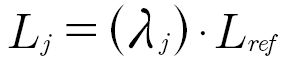
For SWDs, this range is directly conditioned by the number of teeth of the circular spline and usually goes from 30:1 to a maximum of 160:1. In principle, the reduction ratio does not seem to impact weight or size substantially—the whole range is available for most standard sizes—but in practice, lower ratios tend to have lower nominal and acceleration (repeatable peak) torques (Ref. 5). This means that, for a given load, a lower ratio results in larger sizes, as we can see in Table 1.
In pure CDs, the ratio range is about 35:1 to a maximum of 120:1 for sizes compatible with most collaborative applications (outer diameter below 120mm), and it is again a direct result of the number of teeth of the ring gear. As was the case in SWDs, the whole ratio range is typically available for most standard sizes. Still, it does not affect nominal and acceleration torque in this case (Ref. 23). This means that, contrary to what happens in an SWD, reduction ratios within this range do not directly impact gearbox dimensions or weight. Higher torque densities can be achieved by increasing the input speed, but the unbalance resulting cycloidal geometry requires adding a second cycloidal drive and a ring to cope with speeds beyond around 8,000 rpm for small-sized gearboxes (Refs. 24, 25, 26).
CDs with an additional spur-gear pre-gearing stage—frequently termed “rotary vector” or RV cycloids—behave in principle similarly to pure CDs. Still, the additional pre-gearing allows for larger versatility. For collaborative compatible sizes, the reduction ratio range goes here from around 40:1 to 170:1. The reduction ratio does not affect nominal or acceleration torques, equivalent to what happens in pure CDs.
A yet different cycloid alternative is proposed by Onvio and termed a “differential gearing” cycloidal system. In this system, two cycloidal discs are bonded together such that the relative difference in the number of teeth of the two cycloidal discs and the two rings results in a high-ratio configuration when one of the rings is grounded and the other used as an output. Through preloading the rings, minimum backlash can be achieved with this configuration, capable of reaching gear ratios up to 256:1 (Ref. 27).
Planetary gearboxes are extraordinarily versatile, and their configuration has a strong impact on the reduction ratio. The most broadly found configuration is a simple epicyclic in a planetary configuration (Ref. 28), thus with a grounded ring gearwheel. We will be using the term planetary gearhead to refer to this configuration throughout this report. Planetary gearheads have several fundamental advantages that have earned them a clear adoption dominance in industrial settings, including reaching very high-power densities—thanks to the possibility of split power flows between multiple planets—and a very robust topology. Their reduction ratios are though substantially limited to a theoretical maximum of 12:1 (Ref. 29), but, in practice, this range is often reduced to a minimum of 3:1 and a maximum of 8:1 (Ref. 30), as beyond these values, the Hertzian loads—typically on the sun gearwheel—require larger gears that result in unpractically large gearbox sizes.
When larger ratios are required, as is the case for most robotics applications, it is either possible to connect multiple gearheads in series with each other or to diverge to another planetary compound (multistage planets) or coupled (carrier shared between multiple stages) solutions (Ref. 28).
High-Ratio Planetary Configurations
The search for suitable planetary configurations that can achieve higher gear ratios than a conventional planetary gearhead has produced abundant literature. In general, these works tend to highlight the excellence of the conventional planetary gearhead topology, which results in conveniently balanced surface and bending stresses on the gears, better efficiency, and well-balanced load distribution on the different gearbox elements. This ends up making it surprisingly difficult to find configurations that can achieve lower weight and/or size even for substantial reduction ratios.
In 2002, White devoted an article to the derivation of highly efficient two-stage planetary gearboxes in Ref. 31, where he focuses on efficiency and gear ratio. He identified arrangements that avoid internal power recirculation to improve efficiency and bearing life.
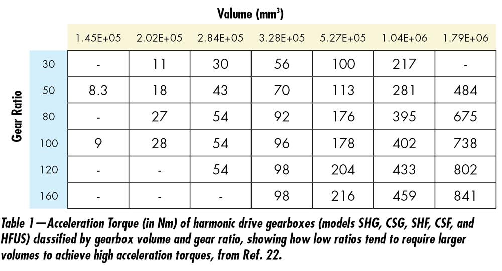
Recent advances in computation provide the opportunity to make systematic reviews of the extensive versatility of planetary gearboxes for a specific objective. This approach is now broadly generalized and has also been applied by Salgado and Del Castillo to complete White’s initial list of configurations in 2014 (Ref. 32). These authors performed a valuable systematic analysis of all possible planetary configurations with four to six links on their ability to provide suitable transmission ratios and combine that with good topological efficiencies. The most interesting configurations are shown in Figure 1. Before that, in Ref. 33, the same authors had also studied the topological efficiency of different planetary configurations. To simplify their calculations, the authors use a reference meshing efficiency of 98 percent assumed constant for all gear meshing contacts in any planetary configuration.
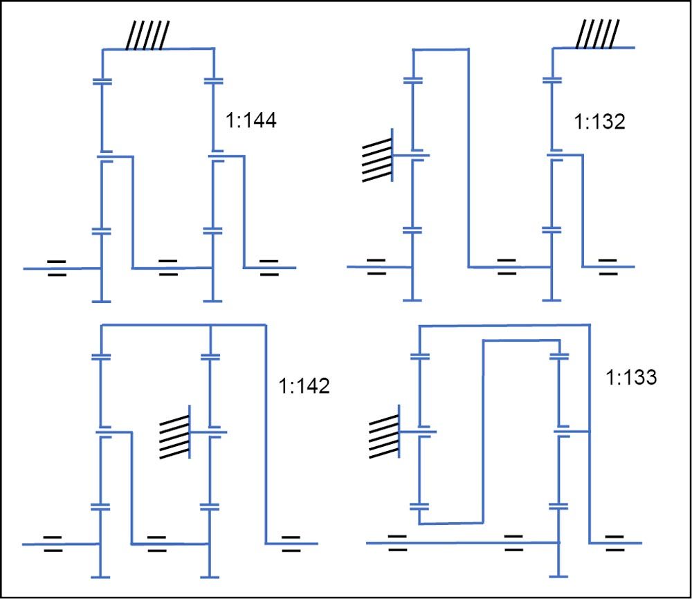
Figure 1—Six-link PGT configurations with the ability to provide high gear ratios (reference values given next to each configuration) with good efficiency, according to Ref. 32. Compared to a Wolfrom configuration, these solutions result in comparable overall gearbox dimensions, but the achievable gear ratios are lower (indicated next to the configuration).
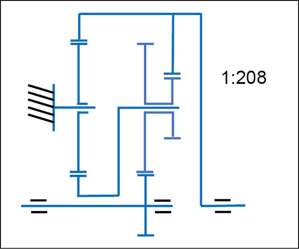
Figure 2—Six-link configurations capable of providing high ratios at the cost of low efficiency (Ref. 32).
Henriot had already tried in 1998 to make a similar analysis of planetary configurations capable of combining high gear ratios and good efficiency (Ref. 32). Henriot’s approach is maybe less systematic but certainly more pragmatic, pointing at the need to incorporate dimensional criteria in this type of analysis. Consequently, Henriot analyzes the potential of selected configurations to achieve high gear ratios while maintaining good efficiency and a compact shape. He proposes a set of configurations with six links and an excellent ability to produce high gear ratios (see Figure 2) which he points leads to low efficiency. In his analysis, he includes specific considerations for each analyzed configuration in terms of (i) potential improvements in the meshing efficiency of each gear meshing contact, (ii) the need to increase the gearbox size to avoid teeth overloads in some particular configurations, and (iii) manufacturing considerations. Considering the individual gear meshing contact efficiency provides a more holistic perspective of efficiency beyond a merely topological impact analysis. Henriot proposes a variation of the conventional gearhead shown in Figure 3, which can produce relatively high gear ratios (1:208) while maintaining good efficiency (above 96 percent, according to Henriot’s estimations).
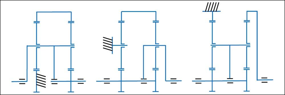
Figure 3—Six-link PGT configuration, derived from the conventional gearhead configuration but capable of providing larger gear ratios while maintaining good efficiency, according to Ref. 32.
In 2013, Kapelevich (Ref. 34) also reviewed some particular high-ratio configurations. He followed again a very practical approach that is more in line with that of Henriot and includes the ability to produce high ratios, efficiency, compactness, and manufacturing considerations.
Mulzer attempts, in Ref. 35, a systematic review of possible high-ratio planetary configurations that could be used in the auxiliary actuation of automobiles. He incorporates a very comprehensive list of requirements in his classification criteria, including cost, efficiency, manufacturing complexity, number of shafts, number of bearings, number of gearwheels, compactness, load capacity, velocities inside the gearbox, bearing loads, and axial length. For a specific reference use case (10 Nm, diameter 45 mm, and axial length 15 mm), he establishes that the most significant potential to achieve high gear ratios in a compact shape is provided by the Wolfrom configuration, which he ultimately selects to build and test his prototypes.
Hoehn and Gwinner put a particular emphasis on lightweight aspects in their analysis in Ref. 37. Comparing three different configurations for three target gear ratios (5:1, 25:1, and 125:1), they demonstrate the advantage of the conventional planetary gearheads in terms of efficiency, but also that configurations using a double ring gearwheel—as in a Wolfrom gearbox—provide the most promising alternative to limit weight.
A high-ratio planetary configuration, which has historically received a lot of attention from gearbox engineers and is often targeted in the previous studies, was first proposed in 1912 by Ulrich Wolfrom (Ref. 38) and is often referred to as a Wolfrom gearbox (the term 3K gearbox is more frequently found in Russian and Japanese literature, whereas in the U.S. this configuration is often referred to as a compound gearbox, due to the use of multistage planet gears). Popular variants of the original Wolfrom gearbox design include the Ferguson (Ref. 39) and the Rossman (Ref. 40) designs, shown in Figure 4, but all of these configurations share a remarkable ability to produce very high gear ratios in a very compact shape and with nicely balanced surface and bending stresses and internal load distributions. The main limitation of Wolfrom—and by extension Ferguson and Rossman—gearboxes is a surprisingly low efficiency that has earned this gearbox the name “mystic gearbox” in Japan (Ref. 41), which we analyze in further detail in “Gearbox Efficiency and Actuator’s Backdrivability.”
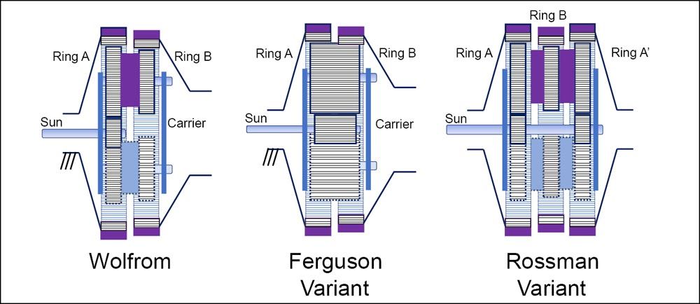
Figure 4—The original configuration proposed by U. Wolfrom in 1912, compared to a variant based on Ferguson’s paradox principle (Ref. 39) using continuous planet tooth geometry and to a variant proposed by Rossman in Ref. 40.
Gearbox Efficiency and Actuator’s Backdrivability
In this section, we will be assuming gear ratios around 100:1 to obtain comparable metrics.
Planetary gearboxes have starting (no-load) torques below 2 percent of the nominal input torque, where the internal configuration of both CDs and SWDs leads to values around ten times larger, in the range of 10 percent to 20 percent (even up to 27 percent for some cycloidal designs) of the nominal torque (Ref. 5). This provides a significant efficiency advantage for planetary gearboxes in robotics, where operation at partial loads is frequent.
Conventional planetary gearheads can reach peak efficiencies beyond 90 percent, assuming gear ratios over 100:1 and particularly if these can be achieved using two-stage configurations. Still, they tend to be larger and heavier than other compact robotic gearbox solutions and have thus a significant disadvantage for modern robotics. Restricting thus the comparison to high-ratio configurations with high torque densities, peak efficiencies can go up to 85 percent for all three compact gearbox technologies considered here and do not represent a significant differentiation factor. CDs achieve high peak efficiency thanks to their fundamentally rolling friction contacts, while planetary and SWD gearboxes take advantage of tooth macrogeometries optimized for low losses. Both CD and SWD gearboxes also benefit from the positive impact on the efficiency of having a similar number of teeth between meshing gears.
The third efficiency parameter in our assessment framework, LPR, shows in Ref. 5 a more favorable starting point for planetary gearboxes and CDs incorporating a pre-gearing stage (LPR values around 30) than for pure CDs and SWDs (LPR values around 100). Conventional gearheads have here a substantial advantage that they cannot exploit again due to their larger size and weight.
In terms of backdrivability, the effect of inertia can be neglected as all considered gearboxes are selected to provide the same output torque and have the same gear ratio. The backdrivability capacity of the three gearbox technologies is thus mainly conditioned by the gearbox’s efficiency at low torques and thus by the starting torque, which has been described in the first paragraph of this section and confirms that the backdriving torque of the planetary gearboxes is substantially lower than for CD and SWD technologies.
Gearbox Hysteresis, Transmission Error, and Noise
SWD transmissions have complex dynamics that include nonlinear viscous friction, nonlinear stiffness, hysteresis, and transmission error. Transmission error is attributed to manufacturing and assembly error and the spline’s deformation in SWDs. Ref. 42 determines the fast Fourier transform (FFT) of the measured transmission error in a Strain Wave SHF17-120-2AS-R-SP Harmonic Drive transmission and identifies the main component at twice the input frequency of the transmission, which correlates well with the manufacturer’s indications that specifies a total positioning accuracy error around one arc·min (Ref. 41) and with the results of Ref. 43. Components at this frequency are typical for misalignment issues in the input shaft. However, in the SWD, it could also be the consequence of unbalances in the oval-shaped wave generator. Although of lower relevance, other significant components in Preissner’s analysis (Ref. 42) correspond to three times the input and output frequencies; the latter typically results from unbalance in the output shaft. These other two frequencies are not explicitly highlighted in the manufacturer’s documentation.
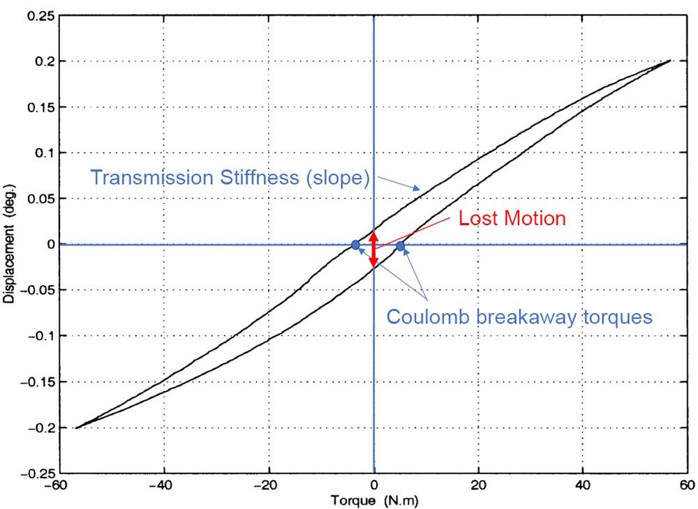
Figure 5—Typical hysteresis curve of a SWD transmission including the effect of torsional stiffness (slope of the curve), Coulomb friction (breakaway torques at zero displacement), and lost motion at 0 Nm torque. Figure reworked from Ref. 44.
A typical hysteresis curve of a SWD transmission is shown in Figure 5 and corresponds to the effects of the transmission stiffness (hysteresis slope) and the Coulomb breakaway friction torque (hysteresis plateau), reflecting lost motion values around 1–3 arcmin.
For CDs, lost motion is also usually specified to be below one arcmin. Still, transmission error amplitude is typically lower (below 70 arcsec) than for SWDs, according to the manufacturer’s indications (Ref. 45). In CDs, transmission error tends to have its primary component at higher frequencies that correspond to the number of pins multiplied by the input frequency, followed by twice this frequency typically due to pin misalignment (Ref. 46). A third important component also occurs at twice the transmission’s input frequency, owing to the eccentric character of the cycloidal gear’s wobbling movement. Wiklo’s analysis (Ref. 47) indicates a larger contribution of manufacturing errors than stiffness variation to the final transmission error, which correlates well with other works that mainly identify the tolerance between the cycloidal disc and the pin-rollers as the most critical (Ref. 48).
Conventional planetary gearheads tend to show higher lost motion values (around 5–10 arcmin) (Ref. 48), which can be reduced to 1–5 arcmin in precision gearboxes, using pre-tensioning and thus negatively affecting efficiency. They also have a more complex transmission error footprint, which is strongly dominated by the multiple meshing contacts between the different individual gears and the related manufacturing errors and changes in stiffness, similar in their origin to what happens in the CDs.
There is very little literature available on high-ratio configurations other than planetary gearheads, the gear bearing drive (GBD)—a Wolfrom-based configuration—analysis in Ref. 49 being one of the few exceptions in which the largest error component was caused by inaccuracies in the output ring gear assembly (3.2 arcmin), followed by the meshing frequency between the planet and the ring gearwheels (1 arcmin). In terms of hysteresis, Ref. 50 measured 2–3 Nm Coulomb dissipation.
None of the engineering catalogs of several consulted manufacturers provide values for CD or SWD transmissions in terms of airborne noise. For planetary gearheads, Neugart specifies a maximum of 60 dB of sound pressure level from 1 m, measured on input running at 3,000 rpm, no-load, and with i=5 (Ref. 48). According to our analysis, this topic is not yet the objective of research literature for CD or SWD gearboxes.
Manufacturing Complexity
There is almost inexistent literature referring to the manufacturing method of the SWD, and little is known in academic circles other than that this manufacturing process is particularly complicated, especially that of the flexspline. Based on patent sources, we have established that this flexible, thin-walled gear with external teeth is manufactured through hot-forging, followed by turning, teeth machining, and shot peening (Ref. 51). In this process, the machining of the teeth is particularly sensitive due to the small modules involved and the flexibility of the blank, which requires precise clamping of both the outer and inner sides of the flexspline (Ref. 52). Another element that complicates manufacture is its effect on the material properties of the diaphragm on the closed end of the flexspline, whose deformation determines the torsional stiffness and has been the focus of active development activities in terms of wall thickness and manufacturing methods, from initial welding to deep drawing (Ref. 53) and ultimately hot forging (even machining for larger sizes, according to nonvalidated sources). The bearing manufacture for the wave generator is also mentioned as particularly challenging in some literature (Ref. 54). According to the manufacturers, this manufacturing complexity is behind the relatively high cost of the SWD transmission. However, it must also be noted that the small number of components of a SWD gearbox represents an advantage, certainly during the assembly process.
The manufacturing process of CDs is better known. It is based on the accurate machining of the different components, typically using 5-axis CNC machines and customized bearing solutions for some manufacturers like Spinea. The manufacturing challenge for CDs is clearly machining accuracy due to their high sensitivity to even the slightest center-distance deviation—a direct consequence of the cycloid teeth geometry—in terms of transmission error and Hertzian loads on the pins. As a result of these demanding manufacturing accuracy requirements, CDs tend to be also expensive, although significantly less than SWDs, according to our own experience.
The RV configuration described in “Reduction Ratio and Torque Density” takes advantage of the spur pre-gearing to adapt the gear ratio maintaining the same cycloidal disk geometry, which reduces manufacturing cost thanks to the larger series. A sensitivity analysis using the Sobol methodology of the RV CD (Ref. 55) shows that the highest influence on transmission accuracy is given the runout of the eccentric cam, while the clearance of the cycloidal disc’s main bearing, pin gear tooth groove error, and accumulative pin gear pitch error have more limited influence. The smallest influence is derived from carrier assembly errors and the bearing clearance between the carrier and frame.
To reduce the mass or to increase torque density, some manufacturers like Spinea use customized bearing solutions where a bearing raceway is integrated within the part. The gearbox’s output is expected to carry out the high output torque along with the bending moment. To avoid using two rolling bearings, cross-rolling bearings are introduced. The solution is well known in the SWD gears.
Manufacturing simplicity is a fundamental advantage of planetary configurations, as highly optimized manufacturing processes, including hobbing, shaping, skewing, grinding, etc., have been developed for involute-profile gears and are currently available for different sizes of manufacturing series and materials (Ref. 56). While substantially simplifying manufacture, involute teeth geometry makes these devices less sensitive to center-distance errors, with load-sharing between multiple planets (mainly affected by manufacturing and assembly accuracy of the carrier) and the manufacture of stepped planets for some high-ratio configurations representing the highest manufacturing challenges. Yet, as we have seen in “Gearbox Hysteresis, Transmission Error, and Noise,” high-precision gearwheels are needed when low transmission errors are required, which tend to substantially impact manufacturing costs and can typically not reach the same levels as CDs and SWDs.
Highlights from Current Research Activities on Robotic Planetary Gearboxes
The PSC Gearbox of Melior Motion
Melior Motion GmbH from Hammeln, Germany, proposes since 2015 a PSC planetary gearbox with three stages, developed explicitly for industrial robots and automation applications based on a patented system to regulate friction wear. The three-stage spur-gear configuration can reach gear ratios up to 200:1 with efficiencies beyond 90 percent (Ref. 57).
Although the exact number of teeth of the gearwheels is not given, it can be estimated to achieve values around LPR=3. Yet, the high-accuracy focus of this gearbox typically involves high-preloading that could condition efficiency at partial loads. This aspect could not be confirmed as the current technical catalog does not include sufficient elements.
According to the manufacturer, this gearbox uses many planets (five) to enable better load sharing and torque densities. Practically though, a PSC gearbox with 325 Nm acceleration torque and a gear ratio of 100:1 weight 5.2 kg, which is considerably larger than CDs of similar characteristics (Ref. 5).
Kuka incorporates this technology in their KR Iontec and Cybertech industrial robotic manipulators (Ref. 7).
The Orbitless Drive
From Vancouver, Canada, Orbitless also proposes a very innovative planetary gearbox. Incorporating a secondary, eccentric carrier capable of providing reaction forces, the Orbitless Drive eliminates the need for a ring gearwheel.
In its basic Prime configuration, the Orbitless Drive results in lower pitch velocities and improved noise behavior and efficiency (Ref. 58). The possible gear ratios achievable with this configuration are limited to approximately half of those of a similar, conventional planetary gearhead (Ref. 59). For higher ratios, Orbitless proposes a design variant that uses a small teeth-number difference on the planets and idler gearwheels to achieve gear ratios up to 15:1.
The Traction Drive
Nidec-Shimpo has recently introduced a novel Traction Drive that minimizes transmission error and noise, taking advantage of its gearless, rolling contact. It can achieve up to 30:1 gear ratios, and the idea is not novel to Nidec, which has been producing this type of planetary gearboxes since 1952, mainly for industrial transmissions. Conventional traction drives (CVTs) are also known for some automotive CVTs. Due to the high contact pressures, they use the capability of some lubricant, traction fluids to solidify (crystalize) in the region where the rollers contact: the crystalized molecules line up regularly and can be used to transfer torque from one of the rollers to the other.
The novelty of this Traction Drive lies in its ability to transfer larger torques with a smaller size, solving a traditional limitation of traction systems and increasing the pressure capability of the rollers by modifying their shape and contact footprint. The current size (100 mm outer diameter) and payload (peak torques up to 20 Nm) are interesting for in-wheel applications as the very low noise level (40–50 dB). Still, no standard product datasheets are yet available (Ref. 60).
The Reflex Torque Amplifier
Genesis Robotics, Canada, recently introduced a gearbox compatible with their LiveDrive motor called the Reflex Torque Amplifier. This gearbox builds on a Wolfrom-based configuration but uses injection-molded gearwheels and can achieve gear ratios up to 400:1.
The underlying topology is that of the Rossman-variant of the Wolfrom gearbox, including a large number of planets. Another exciting aspect of this topology is the use of tapered planet gears and helical teeth to preload the system and reduce noise (Ref. 5).
The Archimedes Drive
IMSystems, Netherlands, is a spin-off of the Delft University of Technology. Their Archimedes Drive follows again a topology based on the Rossman-variant of a Wolfrom gearbox, characterized by the use of toothless rollers, similar to the Traction Drive principle.
The controlled deformation of the roller planets enables torque transmission following an acting principle similar to that of the wheels of a car (Ref. 5).
The Bilateral Drive
The Fujilab, Japan, proposes a highly backdrivable gearbox for robotic applications that is again based on a Wolfrom configuration. With this topology, this device was able to combine gear ratios of 102:1 with forward efficiencies of 89.9 percent and backdriving efficiencies of 89.2 percent. The backdriving starting torque achieved was an impressive 0.016 Nm (Ref. 5). This gearbox is currently under development and is not commercially available yet.
The Gear Bearing Drive (GBD)
The NASA Goddard Space Flight Center, USA, introduced a new concept of a GBD that the Northeastern University of Boston further developed. It is based again on a Rossman-variant of the Wolfrom gearbox topology, adapted to include a carrier-less design and gear bearings that are rolling contacts radially aligning the gears. In this manner, the GBD can be seen as a symbiosis of a traction drive and a Wolfrom planetary gearbox (Ref. 5). This gearbox is also currently under development and is not commercially available yet.
The R2poweR Gearbox Technology
The Brubotics group of the Vrije Universiteit Brussels, Belgium, has recently presented their R2poweR high-ratio, highly-efficient gearbox technology. This technology, initially aimed at human-centered robotics applications, combines the use of low-loss gear tooth macrogeometries with topological modifications of the original Wolfrom planetary gearbox design that enable substantial improvements of the LPR and the meshing efficiency, thus giving the possibility to make very high gear ratios (275:1) compatible with load-dependent efficiencies of 85 percent using 3D-printed, plastic gearwheels. Their most recent results also include promising backdriving torques below 1 Nm for an R2poweR prototype manufactured in steel with rapid-prototyping means (Ref. 18).
Conclusions
This report uses an assessment framework for compact robotic gearboxes to verify if the apparent observation that compact planetary gearboxes could currently initiate a come-back process to participate in the next generation of robots.
We identify six KEAs for collaborative robotics—safety, moderate accuracy, high efficiency, manual configuration, and noise—and how a series of gearbox parameters strongly condition these: reduction ratio, torque density, efficiency (starting torque, peak efficiency, and LPR), hysteresis, transmission ratio, cost (manufacturing complexity), and noise.
Using this framework, we compare the performance of customary gearbox technologies—SWDs, CDs, planetary gearheads, and high-ratio planetary gearboxes—to demonstrate that planetary gearboxes have a better starting position for collaborative robotics than for conventional industrial robots. The main reasons are (i) a larger configuration versatility, which can be used to obtain larger gear ratios in compact shapes—and thus higher actuator torque density—(ii) lower starting torques, which result in substantially better efficiency at partial loads, and (iii) simpler manufacture, which results in better affordability. Further, a quick review of the most relevant research activities in robotic gearboxes seems to provide further evidence that corroborates the vast potential of planetary gearboxes in modern robotic applications.
In conclusion, although this analysis could not provide conclusive evidence of planetary gearboxes becoming dominant in future robotic applications, it demonstrates a high level of attention from the robotics research community and remarkable technological suitability, confirming that planetary gearboxes have a realistic chance for broad adoption in the next generations of robotic devices.

References
- Müller, H. W., 2013, “The Planetary Gear Train,” Vol. 28, Springer-Verlag.
- Freeth, T., Bitsakis, Y., Moussas, X., Seiradakis, J. H., Tselikas, A., Mangou, H., & Edmunds, M. G., 2006, “Decoding the ancient Greek astronomical calculator known as the Antikythera Mechanism,” Nature, Vol. 444, No. 7119, pp. 587–591.
- Wintergreen research, 2020, “Precision strain wave reducer gearboxes and RV and RD reducers. market shares, strategy, and forecasts, worldwide, 2018–2024,”
- Urs, K., Adu, C. E., Rouse, E. J., & Moore, T. Y., 2022, “Alternative metrics to select motors for Quasi-Direct Drive actuators”, arXiv preprint arXiv:2202.12365.
- García, P. L., Crispel, S., Saerens, E., Verstraten, T., & Lefeber, D., 2020, “Compact gearboxes for modern robotics: A review,” Frontiers in Robotics and AI, Vol. 7, No. 103.
- Seok, S., Wang, A., Otten, D., & Kim, S., 2012, “Actuator design for high force proprioceptive control in fast legged locomotion,” IEEE/RSJ International Conf. on Int. Robots and Systems (1970–1975).
- Melior Motion, 2022, “New owner, new opportunities: Melior Motion wants to grow further as part of the Schaeffler Group,” from https://meliormotion.com/news/news/?lang=en.
- García, P. L., Crispel, S., Verstraten, T., Saerens, E., Convens, B., Vanderborght, B., & Lefeber, D., 2018, “Failure mode and effect analysis (FMEA)-driven design of a planetary gearbox for active wearable robotics,” International Symposium on Wearable Robotics, pp. 460–464. Springer, Cham.
- Winter, D. A., 2009, “Biomechanics and motor control of human movement,” John Wiley & Sons.
- Zwyssig, C., Kolar, J. W., & Round, S. D., 2009, “Megaspeed drive systems: Pushing beyond 1 million r/min,” IEEE/ASME Transactions on mechatronics, Vol. 14, No. 5, 564–574.
- Saerens, E., Crispel, S., Garcia, P. L., Verstraten, T., Ducastel, V., Vanderborght, B., & Lefeber, D., 2019, “Scaling laws for robotic transmissions,” Mechanism and Machine Theory, Vol. 140, pp. 601–621.
- Merckaert, K., De Beir, A., Adriaens, N., El Makrini, I., Van Ham, R., & Vanderborght, B., 2018, “Independent load carrying and measurement manipulator robot arm for improved payload to mass ratio.” Robotics and Computer-Integrated Manufacturing, Vol. 53, pp. 135–140.
- Popić, S., & Miloradović, B., 2015, “Lightweight robot arms: an overview.” Infoteh-Jahorina, Vol. 14.
- Dindar, A., Chaudhury, K., Hong, I., Kahraman, A., & Wink, C., 2021, “An Experimental Methodology to Determine Components of Power Losses of a Gearbox,” Journal of Tribology, Vol. 143, No. 11.
- Wimmer, J. A., 2006, “Load losses of spur gears: design influences, maximization of efficiency, tribology,” Doctoral dissertation, Technische Universität München.
- Verstraten, T., Furnémont, R., Garcia, P.L., Rodriguez-Cianca, D., Vanderborght, B., & Lefeber, D., 2019, “Kinematically redundant actuators, a solution for conflicting torque–speed requirements,” The International Journal of Robotics Research, Vol. 38, No. 5, pp. 612–629.
- Chen, C., & Angeles, J., 2007, “Virtual-power flow and mechanical gear-mesh power losses of epicyclic gear trains.”
- Garcia, P. L., Crispel, S., Varadharajan, A., Saerens, E., Verstraten, T., Vanderborght, B., & Lefeber, D., 2022, “R2poweR: The Proof-of-Concept of a Backdrivable, High-Ratio Gearbox for Human-Robot Collaboration,” IEEE International Conference on Robotics and Automation (ICRA2022).
- Zhu, H., Nesler, C., Divekar, N., Ahmad, M. T., & Gregg, R. D., 2019, “Design and validation of a partial-assist knee orthosis with compact, backdrivable actuation,” IEEE 16th International Conference on Rehabilitation Robotics (ICORR), pp. 917–924.
- Verstraten, T., 2021, “Quasi-Direct Drive vs. high-ratio Gearboxes,” https://youtu.be/HLIcopc4pUI.
- Matsuki, H., Nagano, K., & Fujimoto, Y., 2019, “Bilateral drive gear—a highly backdrivable reduction gearbox for robotic actuators,” IEEE/ASME Transactions on Mechatronics, Vol. 24, No. 6, pp. 2661–2673.
- Harmonic-Drive, 2014, “Engineering data catalogue.”
- Spinea, 2019, “TwinSpin, DriveSpin Catalogue 11/2019.”
- Y. Wang, Q. Qian, G. Chen, S. Jin, and Y. Chen, 2017, “Multi-objective optimization design of cycloid pin gear planetary reducer,” Adv. Mech. Eng., Vol. 9, No. 9, pp. 1–10.
- W.-S. Lin, Y.-P. Shih, and J.-J. Lee, 2014, “Design of a two-stage cycloidal gear reducer with tooth modifications,” Mech. Mach. Theory, Vol. 79, pp. 184–197.
- M. Matejic, V. Goluza, M. Vasic, and M. Blagojevic, 2022, “Analysis of Two-Stage Cycloid Speed Reducers Dimensions and Efficiency,” Vol. 4, pp. 171–181.
- “ONVIO Zero Backlash Speed Reducers—Catalogue.” [Online]. Available: https://www.onviollc.com/Files/pdf/onvio_catalog_zero-backlash-speed-reducers-1.pdf.
- ANSI/AGMA 6123-C16, 2016, “Design Manual for Enclosed Epicyclic Gear Drives.”
- Jelaska, D. T., 2012, “Gears and gear drives,” John Wiley & Sons.
- Arnaudov, K., & Karaivanov, D. P., 2019, “Planetary gear trains,” CRC Press.
- White, G., 2003, “Derivation of high efficiency two-stage epicyclic gears,” Mechanism and Machine Theory, Vol. 38, No. 2, pp. 149–159.
- Del Castillo, J. M., 2002, “The analytical expression of the efficiency of planetary gear trains,” Mechanism and Machine Theory, Vol. 37, No. 2, pp. 197–214.
- D. R. Salgado and J. Del Castillo, 2005, “Selection and design of planetary gear trains based on power flow maps,” J. Mech. Des., Vol. 127, No. 1, pp. 120–134.
- G. Henriot, 1998, “Gears and planetary gear trains,” Brevini.
- Kapelevich, A., & AKGears, LLC, 2013, “High gear ratio epicyclic drives analysis,” Vol. 3, No. 10.
- Mulzer, F., 2010, “Systematic high-ratio coaxial gears,” Doctoral dissertation, Technische Universität München.
- Höhn, B. R., Stahl, K., & Gwinner, P., 2014, “Improved Efficiency for High-Ratio Planetary Gear Transmissions: Low-loss Wolfrom transmission for wind turbines,” Getriebe aktuell, Vol. 1, No. 1, pp. 6–11.
- J. Looman, 2009, “Gearboxes: basics, construction, applications in vehicles,” Springer Science & Business Media.
- Golenko, A., 2009, “3K Mechanical Paradox transmissions: The shaping of the meshing zone for better efficiency.” Archives of Civil and Mechanical Engineering, Vol. 9, No. 2, pp. 39–46.
- US1970251A, Allen M. Rossman, “Mechanical Movement”, 1934, U.S. Patent Office.
- K. Hori and I. Hayashi, 1994, “Maximum efficiencies of conventional mechanical paradox planetary gears for reduction drive,” Trans. Jpn. Soc. Mech. Eng., vol. 60, no. 579, pp. 3940–3947.
- Preissner, C., Royston, T. J., & Shu, D., 2012, “A high-fidelity harmonic drive model.”
- Quiroga, C. W. P., Abba, G., Antoine, J. F., Raharijaona, T., & Garrec, P., 2021, July, “Load-dependent Friction Laws of Three Models of Harmonic Drive Gearboxes Identified by Using a Force Transfer Diagram”, in 12th International Conference on Mechanical and Aerospace Engineering.
- Dhaouadi, R., Ghorbel, F. H., & Gandhi, P. S., 2003, “A new dynamic model of hysteresis in harmonic drives. IEEE Transactions on Industrial electronics.”, 50(6), 1165-1171.
- Nabtesco, 2018, “Precision reduction gear RV.”
- Kawahara, S., Ohishi, K., Miyazaki, T., & Yokokura, Y., 2013, “Vibration suppression feedback control on angular transmission error of cycloid gear for industrial robot,” IEEE International Conference on Mechatronics (ICM) (pp. 859-864).
- Wikło, M., Król, R., Olejarczyk, K., & Kołodziejczyk, K., 2019, “Output torque ripple for a cycloidal gear train,” Proceedings of the Institution of Mechanical Engineers, Part C: Journal of Mechanical Engineering Science, Vol. 233, Nos. 21–22), pp. 7270–7281.
- Pham, A. D., & Ahn, H. J., 2016, “Lost motion analysis of one stage cycloid reducer considering tolerances,” International Journal of Precision Engineering and Manufacturing, Vol. 17, No. 8, pp. 1009–1016.
- Neugart AG, 2020, “PLE Economy Line. Catalogue.”
- Brassitos, E., & Jalili, N., 2018, “Identifying stiffness, friction, and kinematic error signature in gear bearing drive transmissions,” International Design Engineering Technical Conferences and Computers and Information in Engineering Conference, Vol. 51814, p. V05BT07A045, ASME.
- DE 10 2015 102 651 A1, 2015, Kobayashi, M., “Flexible external gearwheel for a strain-wave gearbox and process to manufacture such,” Harmonic Drive Systems Inc., Tokyo.
- CN111975301B, Yang, H., “Flexible gear machining method,” CenTech Eg. Co. Ltd., Sichuan.
- US4,934,212, 1990, Hofmeister C.A., “Harmonic drive flexspline manufacture”, Quincy Technologies Inc., Connecticut.
- Raviola, A., De Martin, A., Guida, R., Jacazio, G., Mauro, S., & Sorli, M., 2021, “Harmonic drive gear failures in industrial robots applications: An overview,” PHM Society European Conference, Vol. 6, No. 1, pp. 11–11).
- L. Han and F. Guo, 2016, “Global sensitivity analysis of transmission accuracy for RV-type cycloid-pin drive,” J. Mech. Sci. Technol., Vol. 30, No. 3, pp. 1225–1231.
- Klocke, F., & Brecher, C., 2016, “Gearwheel and gearbox technology: design, manufacture, inspection, simulation,” Carl Hanser Verlag GmbH Co KG.
- Melior Motion, 2020, “Precision gearboxes of the highest level,” catalog.
- US 2017/00 74 354 A1, 2017, L. J. Stocco, “Orbitless gearbox.”
- L.J. Stocco, 2016, “The orbitless drive,” ASME International Mechanical Engineering Congress and Exposition, ASME.
- Nidec-Shimpo, 2017, “Traction Drive: breaking through the limitations of gear technology,” brochure.


 Power Transmission Engineering is THE magazine of mechanical components. PTE is written for engineers and maintenance pros who specify, purchase and use gears, gear drives, bearings, motors, couplings, clutches, lubrication, seals and all other types of mechanical power transmission and motion control components.