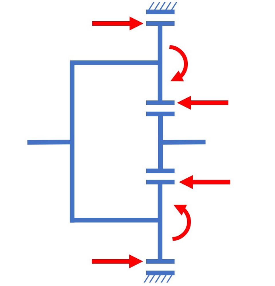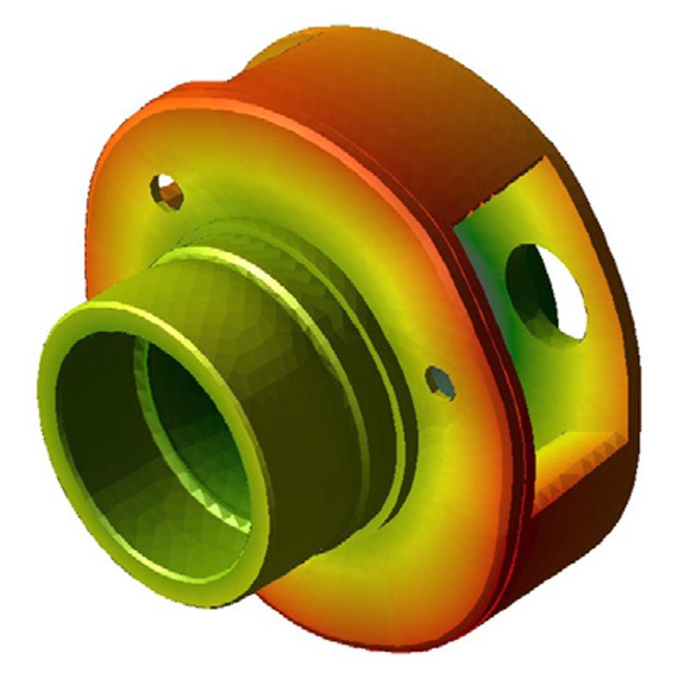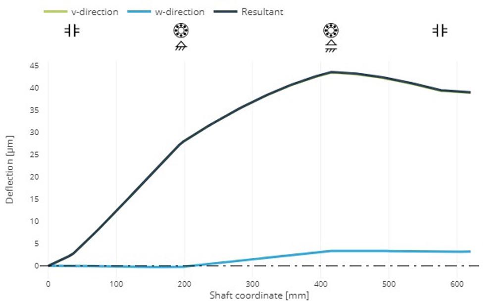
Figure 2—Deformed planet carrier (top) and planet pin deflection (bottom).
The accuracy of the results of the component calculations using the FE method greatly depends on the selection of suitable boundary conditions and the meshing. In the FVA-Workbench, the meshing of the component and definition of the coupling points is largely automated (one-click FEM method) and is adapted to the specific gearbox components to be calculated. Components are loaded and positioned in the 3D Model, with the system providing user guidance for support. This method ensures that reliable and reproducible results can be achieved, even without special FE knowledge.
Calculation of rolling bearing stiffness and operating clearance in the FVA-Workbench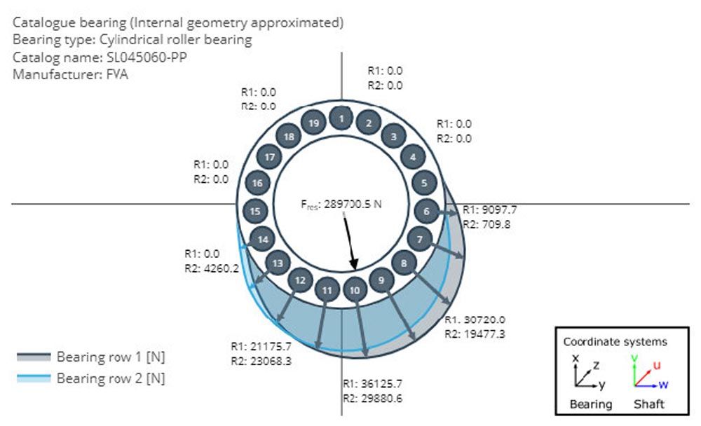
Figure 3—Load distribution in a planetary bearing.
In the FVA-Workbench, the stiffness and operating clearance of rolling bearings are calculated using methods developed in FVA research projects (Refs. 3, 4). These are based on detailed analysis of the contact between the rolling elements and the bearing rings. As part of these research projects, the methods were validated by test stand experiments and by comparing the results to those of the bearing manufacturers.
Calculation example
Below, the gearbox model from the FVA Nacelle Research Project (Ref. 1) is used to demonstrate the importance of a detailed deformation analysis for calculation of the longitudinal load distribution and the design of face modifications for planetary gears.
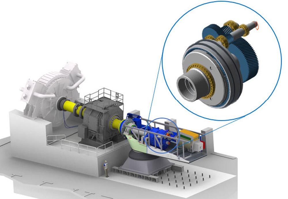
Figure 4—FVA Nacelle Research Project (Ref.1) test stand setup and FVA-Workbench gear model.
Figure 5 compares the longitudinal load distribution of the planetary stage in the sun-planet mesh for three different calculation variants:
Variant 1: Here, the longitudinal load distribution is shown based on a simplified calculation, without consideration of the deformation of the planet carrier and deflection of the planetary bearings, as is still often used in simplified methods. In the FVA-Workbench, the torsional stiffness of the planet carrier and the radial stiffness of the planetary bearings can be set to a very high value. The torsional deformation of the sun gear (blue area) is dominant compared to the tilting of the planets (green area). This method produces a calculated overload at the generator-side end of the gear.
Variant 2: An additional face modification in the form of a helix angle modification with symmetrical crowning is considered in this calculation. This face modification is designed to produce a uniform load distribution when combined with the deformations from the simplified calculation in Variant 1.
Variant 3: This longitudinal load distribution is the result of the detailed calculation of the deformations of the planet carrier and the planetary bearings, which are to be compensated by the flank modifications determined from the simplified calculation. In this case, the greater tilting of the planet gear leads to a local overload on the rotor-side end of the gear.
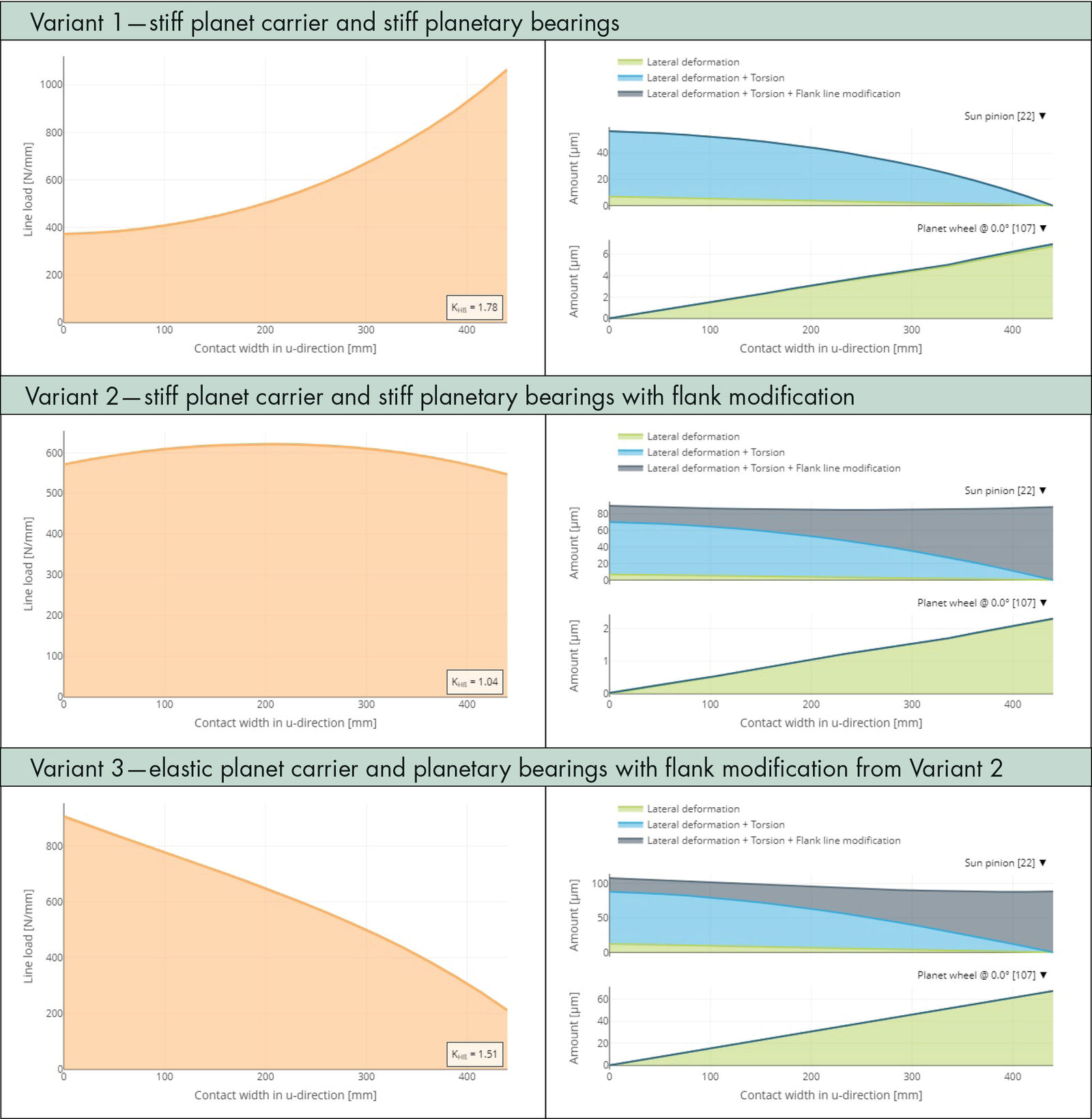
Figure 5—Sun-planet mesh load distribution (left) and deformation amounts along the face width (right).
For planetary stages in which a gear modification that was designed using simplified methods is combined with low material reserves, damage patterns may occur with large pitting areas on the rotor-side end of the sun gear. Figure 6 shows an example of such a damage pattern, which can be attributed to a local overload, on a sun gear shaft from the main gearbox of a wind turbine in the 1.5 MW class, like the calculation model used.
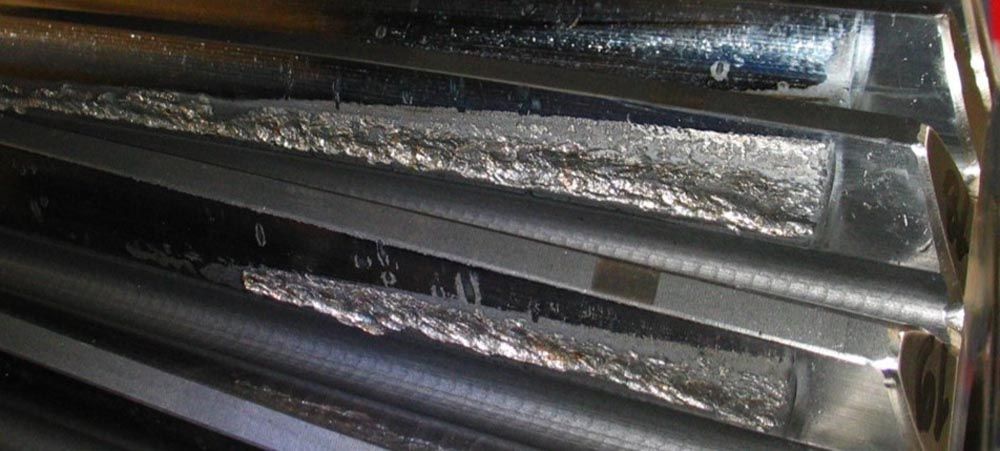
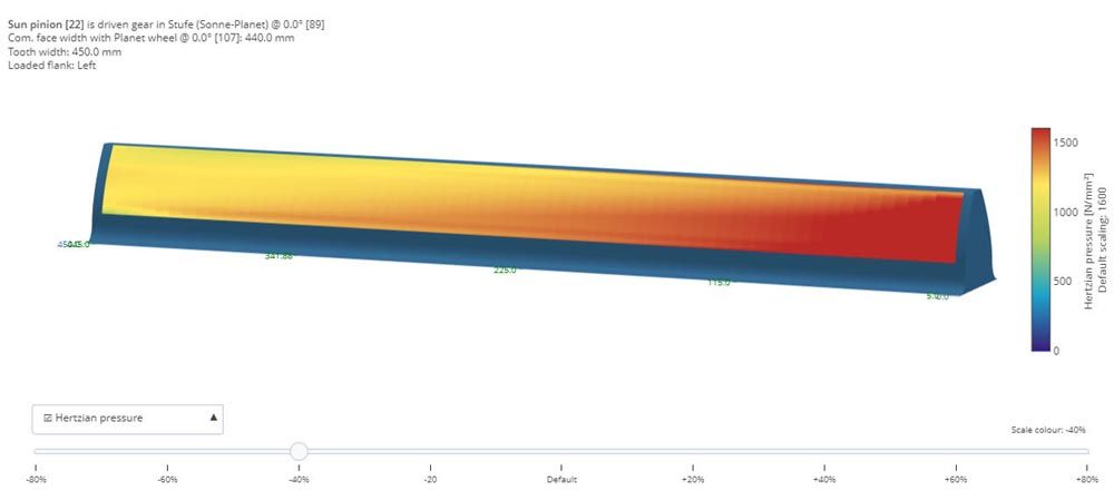
Figure 6—Practical example of a damaged sun gear (top); 3D pressure distribution, Variant 3 (bottom).
Conclusion
The FVA-Workbench makes it easy to consider all relevant influencing factors in the design of gear modifications for planetary stages. This allows for weight- and cost-efficient design while also ensuring high operational stability. 
References
- FVA Research Project ٧٣٠—Wind Turbine Drive Component Loads.
- FVA Research Project ٧١١ I: Integration of Elastic Casing Structures into Gear Design with RIKOR and Visualization of the Complete Transmission System in the FVA-Workbench.
- FVA ٣٦٤ I to V—LAGER ٢ Subroutine.
- FVA Research Project ٩٠٩—Rolling Bearing Calculation Transfer.