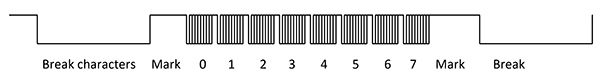
DMX-512: Where lighting and special effects are included, DMX-512 is the standard for digital communication. DMX-512 controllers can control lighting flood orientation, color, intensity, smoke machines, camera location and shutter, focus, and the props and characters, so that these can all be synchronized to the camera. DMX-512 is a well-defined serial stream with a RS-485 hardware format. The most basic format uses a 250k-baud (4uS/bit), 1 start bit, 8 bit data, no parity, 2 stop bit format (44uS per “slot”) with a minimum 2 slot (88uS) break to indicate the starting of a new frame. The first character defines the “universe” (which devices are to respond to the frame) as well as special packets, and the remaining up-to 511 slots carrying data to control the various devices. More advanced versions of DMX-512 allow for diagnostics with the controlled devices being able to respond to special query packets. Multiple slots can be combined to allow 8, 16, 24, and 32 bit data to be represented in the stream; these are normally configured as big-endian (MSB sent first). Each device checks the sent universe (first byte in the frame) addressing that device, and then counts off the bytes to see which bytes or groups are applicable to that device. Some devices include the ability to check the first 100 slots to help avoid corrupted data. Although DMX-512 can convey up to 512 slots, shorter frames are commonly used to allow the frames to be fast enough to allow a frame of data to by synced to one shutter of the camera. Figure 3 shows a short frame, starting with break characters to mark the start of the frame, the mark after frame to let the serial converter settle after the break, and then the slots (8 total in this example). The frame then repeats.
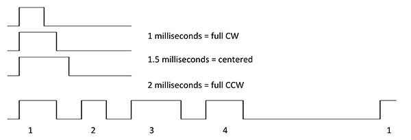
Figure 3: PWM Signals and Multiplexing
Analog control: Earlier shows also used analog channels to control motions, with a dedicated analog channel and its return used for each actuator. These were commonly either 0-10v or +/- 10v signals. The signal is sent relative to the dedicated reference signal with a differential amplifier used to remove ground difference between the show controller and the individual axis electronics. Analog control requires many individual wire pairs to be run and can have ground noise issues. As such, analog control is being designed in less frequently, while other digital methods are gaining market share.
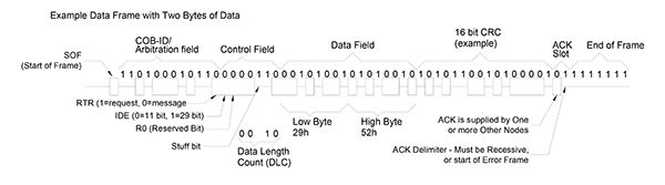
CAN protocol: Many shows and ride props are starting to go over to CAN (Controller Area Network). This protocol originated at Bosch for control of under-the-hood electronic control units, and was designed with multiple levels of protection to help ensure delivery of the correct data. The data is carried as a differential signal, on the CAN-H and CAN-L signal bus. Two electrical states exist on the bus — “Dominant” — which represents a “0” level and has CAN-H driven high and CAN-L driven low, and “Recessive” where none of the nodes is driving the bus, and the terminating resistor pull CAN-H and CAN-L to a small residual differential voltage. Each driver is essentially “diode-or’ed” on the bus, allowing multiple can drivers to simultaneously assert a dominant level without loss of signal. After a quiet (recessive) period between frames, any device with a message to send asserts a dominant start bit. All other devices having a message to send synchronize to this start bit and also assert their own start bits. The identification for the packet — called the COB-ID — is then sent, with each of the devices having a message sending each bit from high to low, while also monitoring the CAN bus. Figure 4 shows three nodes all trying to send a message. As long as each node sees the bus in the same recessive or dominate state that node has driven, the node may proceed to the next bit. If the state does not match, then that node loses the arbitration and must wait for the frame to complete before trying again. This allows the highest priority frame (lowest numbered COB-ID) to proceed on its first try while lower priority messages are delayed until no higher priority message is vying for the bus. Multiple types of frames are defined allowing different modules to communicate in one-to-one communications, as well as one-to-many (or none) broadcasts, and background status (heartbeat) messages as well as network management control. Each frame can carry 0 to 8 bytes of data for basic CAN; newer CAN-FD allows longer data fields up to 64 bytes, as well as higher data rates for the data fields and data CRC portions of the frame. An important aspect is that a particular COB-ID may only be assigned to a single device on the bus to allow proper arbitration.
Figure 5 shows a full frame with 2 bytes of data for the basic CAN signals (non-FD). Not shown in the figure is bit-stuffing: all of the units on the bus resynchronize their timing with each transition of the bus to compensate for differences in their internal clock speeds. To prevent too much drift in their relative timing, the protocol does not allow more than 5 bits of the same polarity before a bit of the opposite polarity is inserted (stuffed) into the frame. These extra bits provide the transitions needed to resynchronize timing between units. These extra bits make the frame time slightly longer dependent upon the data present, and are discarded when the frame is received.
Both real-time show information and back channel diagnostics can share the bus by proper assignment of priority through the selection of which COB-ID numbers are assigned to which functions. CANopen focuses on how these COB-IDs are used as well as standardizing the various interactions between modules. There are multiple CAN protocols with varying flexibility.
Ethernet: Ethernet is continuing to become less expensive, but not to the levels of the already described protocols. Higher level automation supports the added size and cost, but most animatronics has not yet made that jump to the lowest level of actuator. Ethernet, however, is commonly used to drive one level up from the bottom actuator, bringing show data to the analog output cards, CAN output cards, and DMX output cards, with each of these cards commonly controlling 8 to 32 actuators.
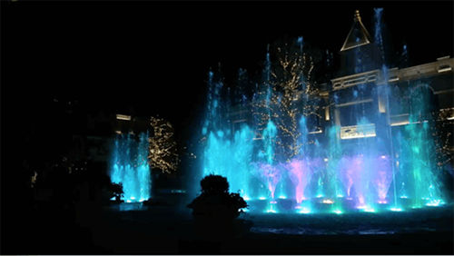
Figure 6: Water Fountain Show
Combination: Multiple communication types may be combined. Figure 6 shows a water fountain show. This application used both DMX and CANopen. The DMX was used for the main show choreography. This included controlling pumps, pointing the fountain head in polar coordinates, setting light colors, and pointing/spinning certain fan type nozzles. CANopen was used to calibrate each station. Each fountain is mounted to concrete set within the fountain. The nozzle needs to be calibrated to compensate for tilt — front and back and side to side. It also needs to be calibrated for rotation so all fountains agree on what is zero degrees — “North.” Calibrating each fountainhead then makes it much easier to program the show rather than having to compensate these variations inside the show itself. This also eases maintenance if a fountain must be replaced. Recalibrate the new fountain head and the show stays the same. The local axes monitored both their primary DMX position slots, some diagnostic control slots, and their paired axis. The two axes interacted via a lever arm, which required adjusting the position of each actuator to compensate for the effects of the lever arm. Again, doing this compensation at the motor controller level allows the show to output desired angles to make programming multiple shows across the many fountains much easier. The CANopen backchannel allows diagnostic functions to run while the show is active without affecting timing of the show.
Actuators: The actuators cover a wide range of speeds, sizes, and power ranges. These can vary from the tiny actuators designed for RC planes to multi-horsepower motors to move props.
At the low end are open loop air cylinders which are switched on and off. The rate of movement may be adjusted by controlling the rate of air flow, but changes in friction can affect the motions. There are also closed loop air cylinders which use feedback and proportional valves to make the motions better controlled. The quality of motion and the price both go up. The moving seal can limit the no-maintenance life of both of these actuator types, as can the quality of the air supply.
The small RC plane-type controllers are commonly a small brush motor with potentiometer feedback, although brushless motors with absolute feedback are available. These are usually limited to 1-2 millisecond PWM control. These compact actuators greatly gear down the motor, trading speed for higher torque. The small size can handle functions like eye and eyelid movement, small light props such as ears and tails. The DC brush motors tend to have a shorter life — from a few hundreds of hours, to a few thousands of hours for high-quality units. Brushless motors commonly go 10k to 20k hours at the low end to significantly more — the quality of any gear train starts to dominate the life expectancy at that point.