The nominal shape of the waveforms driving the motor can substantially affect the acoustical noise. For a 3-phase motor, 6-step commutation with a trapezoidal drive abruptly switches the current forward or reverse for a particular phase, with common drivers only limiting the rate of rise of current by the inductance of the winding and the applied voltage. A 12-step trapezoidal commutation technique adds a zero current step for each phase before reversing the direction of the current. For hybrid motors, the equivalents are full-stepping and half-stepping. The abrupt current changes give rise to acoustical noise both at the fundamental and at many harmonics of the commutation rate. The noise is not only caused by the previously mentioned magnetostriction effects and deformation of the case, but also by the sudden jerk (high rate of change of torque) associated with rapid changes in the winding current torquing the shaft, often with the resulting ringing each time the motor commutates to the next phase combination.
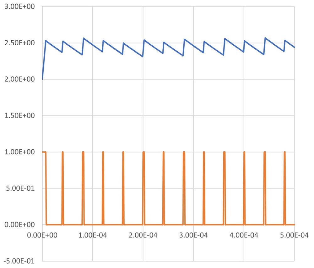
Figure 3 Subharmonic Oscillation
A shorter drive cycle results in more time in the decay portion of the cycle, requiring a longer drive cycle the following PWM cycle. That longer drive cycle results in a shorter decay portion, so the current starts higher and the following PWM cycle requires a shorter drive cycle. This results in a 10 kHz subharmonic which is audible even though the PWM is operating at 20 kHz.
In the hybrid motor realm, there are microstep drives which more closely approximate a sine wave by adding many finer steps to the current waveform to reduce the magnitude of each step change. However, most of the drivers use a current control loop that still tries to achieve the next step in the minimum time possible, turning the driver full on until the next desired current plateau is attained. The conventional 3-phase brushless motors are similar with sinusoidal commutation. Note that the design of the motors for trapezoidal 3-phase operation are different than those for sinusoidal commutation, the former having back-EMF waveforms that are typically much squarer than the sinusoidal back-EMF waveforms associated with sinusoidal drive optimized motors. Hybrid motors, similarly, are optimized for either full stepping (50:50 laminates) or for microstepping (48:50 laminates or 50:52 laminates for the common 1.8-degree stepper). When plotting the back-EMF of phase A versus phase B, a full step (50:50 laminate) will plot as almost a square with slightly rounded corners, while a microstep optimized motor will plot as almost a perfect circle.
The noise level generated by a motor may be minimized by minimizing the rate of change of the current in the winding, making it a function of the motor speed, rather than having the current loop attempt to perfectly follow the square change with each new step on the microstep table. This may be done by altering the operation of the current control loop to also utilize a motor speed estimation such that at lower speeds, a lower rate of change is implemented, and saving the rapid changes for higher speeds where motor torque would suffer if the current were not changed at a sufficient rate.
Chopping Drives
Most modern drives use pulse width modulation (PWM) control to vary the currents in the motors. Most current control loops, for both hybrid motors and 3-phase brushless, are responsible for a couple of additional noise generation modes.
The first noise is called “sizzle” and is a caused by amplification of the noise from the measurement of the current being controlled. To minimize heating of the current sensing resistors, very low value resistors are typically used. The resulting voltage from the sensed current passing through the low value resistor is relatively low, so voltage gain must be set fairly high. The noise may be significant compared to the measurement, causing the control loop to try to react to the perceived current rather than the actual current. The result is the current loop amplifies the measured noise, causing the motor to emit a hissing or sizzling noise.
The second noise related to the chopping drive is a squeal. Although it is common to operate the PWM drive at 20 kHz to 25 kHz, which is typically above human hearing, it is common to hear significant noise in the 6 to 10 kHz range, which is quite audible to humans. The cause of the noise is an instability called subharmonic oscillations. PWM drives for motors are typically operating as a form of buck converter, as the short-term average voltage needed at the winding to maintain a given current is commonly significantly less than the power supply voltage. It is common that these subharmonic oscillations occur at ½ or 1/3 of the chopping frequency, thus a 25 kHz chopper may easily produce significant noise at 12.5 kHz or 8.33 kHz, both of which are quite audible. There are many articles on subharmonic oscillations in buck converts that go into to significant detail, but here is a brief simplified discussion.
The PWM drive drives the winding either at the power supply voltage or shorts the winding or may drive the winding in the reverse direction with the power supply voltage (if the current is already too high). At the beginning of each PWM period, the driver determines if the measured current is higher or lower than commanded current. Assuming the motor is moving slowly or is stationary, the current will have generally decayed due to resistances in the transistors and windings, and the driver will need to turn “on” the drive for a period of time until the current measured again reaches the commanded current. The driver will then short the winding (regeneration mode) until the next PWM cycle begins.
To understand how the subharmonic oscillation sustains, assume this first cycle started with the current somewhat lower than average. The “on” time of the PWM will need to be longer than average to bring the current back up to the commanded level. The current will then decay until the next PWM cycle begins. Because the “on” time was longer than average, the decay time (recirculate mode) remaining for that PWM period must be shorter if the PWM frequency is constant. The shorter decay time will cause the starting current for the subsequent cycle to be higher than for the last cycle. The PWM on time will be shorter, as it does not take as much time for the measured current to reach the commanded current level before the driver goes again into recirculate mode. This means that more time will be spent in the recirculate mode for this cycle, resulting in a lower measured current at the start of the subsequent cycle. This long cycle, short cycle as described would be a second subharmonic, or would happen at half of the chopping frequency. By a similar process, you can also commonly cause a third subharmonic oscillation. The resulting periodic current variation causes an audible squeal (or “singing”) which can be very irritating when exposed to it for a full work shift. The high frequency of this current variation generally makes motor a more effective speaker whereas very low frequency variations generate little noise.
A Smarter Current Loop
The rapid change in current at commutation, sizzle, and subharmonic oscillation may all be overcome by using a current estimator modeling the motor rather than directly measuring the motor current. The voltage applied to the motor, the motor inductance, the motor resistance, the motor back-EMF, and the motor speed and position may be used to estimate the current. The resulting current loop does not have sizzle, and does not have the subharmonic oscillation squeal, and may be further configured to limit the rate of change of current to only that required for the instantaneous motor speed.
Control Method
The motor noise may also be significantly affected by how the motor is controlled. An open loop step motor is typically driven at full current regardless of the load. The torque takes a step at each step or microstep change, resulting in a significant jerk at each transition. Both low speed resonances and mid speed resonances may create extra motion oscillations, resulting in significant acoustical noise. The magnetostriction and attraction forces are also maximized by using full current, again contributing to noisy operation. Servo control uses only the current needed to generate the desired motion. This minimizes both the current and the rate of change of the current. Electronic damping can further reduce the vibration of the load when rotating. When combined with a smart current loop, the motor acoustical noise can be greatly reduced.
Summary
The resulting motion, of both hybrid servomotors and 3-phase AC brushless servomotors—both using sinusoidal commutation—can be essentially silent operation up to a few hundred RPM. When testing one QuickSilver NEMA 17 frame hybrid servomotor, we used a sound meter that was designed to be used at a 5-foot distance for its calibrated measurement at only 3 inches (20x closer) in an attempt to get any sound to even register. As the sound energy halves for each doubling of distance (square law), so sensitivity doubles (~ 6 dB) for each halving of distance. We saw a meter reading of less than 50 db with the meter 20x closer than calibration distance, indicating the noise contributed by the motor was likely less than 24 dbA, virtually silent operating at a few hundred RPM.