


Designing Plastic Components for Power Transmission Engineers
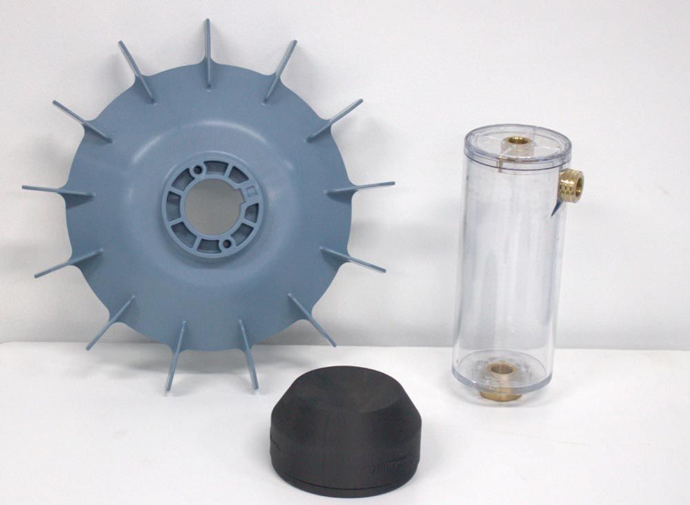
Figure 1—Sumitomo Cyclo Cooling Fan (left). Sumitomo Safety Cover (center). Sumitomo Oil Fill Cup (right).
Steel, iron, and aluminum are the dominant materials in the mechanical power transmission industry for good reason: high power density requires the high strength and stiffness of metallic materials. Plastics, however, offer valuable features that should be utilized for good gearbox design. Their low density, low cost, and corrosion resistance properties are ideal for low-stress applications such as fans and covers; transparent plastics are ideal for oil expansion tanks to aid operators in visualizing oil level and appearance from varying distances; high-strength plastics can be used as couplings between metallic components to eliminate fretting wear. Despite their value, plastics are still used infrequently enough in the gear industry that engineers often mistakenly design plastic components as if they were metallic.
Designing plastic components has never been easier. Guides to the basic concepts of plastic design, such as wall thickness, draft, ribbing, etc. are readily available, and fully automated design analysis of a component can be generated at many rapid manufacturing websites. While these resources allow anyone to design a manufacturable plastic component easily, they typically don’t guide how a plastic component might interact within an assembly or environment.
Plastic materials have unique interactions that should be considered before design finalization. As noted herein, some common pitfalls should be avoided and mitigated during the first iteration of a plastic prototype design to maximize success.
Thermal Expansion
Thermal expansion is a common consideration with metallic components when designing press fits, setting bearings, etc. But consider that plastic materials typically have a thermal expansion rate 5 to 10 times higher than steel: this can cause some issues. When plastic components operate on a shaft or within a bore, resultant fits should be calculated. Furthermore, plastic thermal expansion rates are often high enough that dimensional change due to temperature should be included in tolerance analyses or “stack-ups” to ensure the intended final fit. For example, depending on the specific grade of plastic, a 50 mm long component made of Nylon 66 will expand up to 0.25 mm when undergoing a 50°C temperature rise. Thermal expansion could be contributing to the tolerance stack-up just as much as the tolerance itself! When analyzing thermal expansion, it’s vital to ensure data accuracy: use the actual data sheets for the chosen material or standardized sources like CAMPUS (campusplastics.com), as material properties of plastics can vary wildly even within the same polymer family (Ref. 1).
Water Absorption
Plastic components are injection molded, 3D-printed, or otherwise manufactured with the raw material completely dry. After the component is released from the mold, it begins absorbing moisture from the ambient air, until it achieves equilibrium with the environment. This is the state at which plastic components are physically measured, and mechanical properties such as strength and hardness are reported. However, if a component’s operating environment has higher moisture content, e.g., it’s submerged in water or an environment with heavy splashing, the plastic will absorb more water. This additional water content impacts the component’s mechanical properties and causes it to swell physically. Most plastics only change slightly due to this phenomenon, but many families of Nylon (PA) are affected significantly, in some cases growing as much as 1 percent. Referencing the previous Nylon example, the 50 mm long Nylon 66 component could grow 0.5 mm from moisture content alone. This can cause similar issues to thermal expansion and needs to be accounted for by choosing the right material in applications that may experience high moisture content (Ref. 2).


 Power Transmission Engineering is THE magazine of mechanical components. PTE is written for engineers and maintenance pros who specify, purchase and use gears, gear drives, bearings, motors, couplings, clutches, lubrication, seals and all other types of mechanical power transmission and motion control components.