Design of Plastic Microgear Teeth for Mass Production with High Manufacturing Tolerances for a Medical Device
Design of Plastic Microgear Teeth for Mass Production with High Manufacturing Tolerances for a Medical Device
Jürgen Strüber
Introduction
Microgears (module < 0.2 mm) for prototype mass production
have very large production tolerances in comparison
with the gearwheel size. The tolerances are of the order of
±1.5% of the nominal size. Fault-free operation, i.e. — flank
clearance and sufficient contact ratio — must be ensured
over the entire tolerance range. A transverse contact ratio
of greater than 1, which represents a conventional design
rule, is no longer achievable with such large tolerances.
These framework conditions set new requirements for the design
and also the evaluation of microgears.
Here a tolerance-insensitive design is presented, which
has a large absolute tooth depth (in mm) and a large relative
tooth depth (in modules). The modifications made here
ensure a smooth start to meshing over the entire tolerance
range, even with a transverse contact ratio of less than 1.
Microgears have been
available for decades, as, for example, in small wrist-watches. Over the last
few years the range of use has grown to include other sectors such as digital
cameras, model-building or medical technology. Especially in the latter sector,
there is an increasing number of short-lived mass-production products which
must be both inexpensive and simultaneously offer very high reliability over
the specified product lifetime. Typical examples are blood glucose measuring
devices and insulin pumps for diabetics: devices no bigger than a mobile phone
house a mechanism that is capable of providing and evaluating measuring strips
or extremely precise micropumps driven by microgear motors.
According to VDI 2731 Microgears Basic Principles (Ref. 1),
the boundary between precision engineering gears and
microgears is a module of 0.2 mm. With micro-gearwheels,
just as for precision engineering gearwheels, the involute
form is the favored tooth shape (Ref. 1). However the tolerance
dimensions cannot be reduced to the same extent as the
main dimensions, and thus increase relative to the component
size, the smaller the gear unit becomes. Plastic injection
molding is primarily used as the production process,
which intrinsically has relatively wide production tolerances.
Problems and the Resulting Definition of a Task
The production-inherent tolerances of micro-gearwheels in
mass production can certainly amount to 1.5% of the nominal
dimension. In addition, there are large center distance
tolerances due to plastic housings and long tolerance chains.
The main requirements of the tolerance design are a tooth
flank backlash greater than zero, and sufficient contact ratio
over the entire tolerance range.
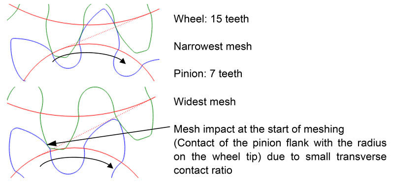
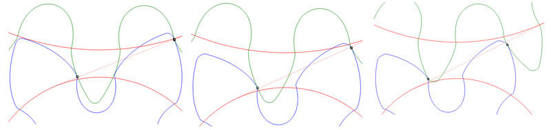
Figure 1 shows gear meshing according to a conventional
design similar to DIN 58400 (Ref. 2) , with tolerances typical
of a microgear. According to conventional evaluation,
the transverse contact ratio must be at least 1 over the tolerance
range. For the widest mesh (Fig. 1, right) there is a
transverse contact ratio of less than 0.6, with a correspondingly
hard impact at the start of meshing. The results are
noisy running and severe wear. Consequently a gearwheel
design is required that ensures operating reliability — even
with large tolerances.
Figure 1 — Conventional design, similar to DIN 58400 (Ref. 2).
Design of Tolerance-Insensitive Toothing
The following requirements should be adhered to:
Gear ratio: approx. 2
Plastic gearwheels and housing parts can be
mass-produced using a (micro-) injection molding
process
Tolerances for tip diameters, tooth thickness and center
distance, as already presented
Straight-toothed
A design insensitive to large center distance and gearwheel
size tolerances requires a large absolute tooth depth in millimeters;
i.e. — a trend towards a large module and a small
number of teeth is necessary. With a small number of teeth,
the tooth depth relative to the module is limited by undercut
and by the tooth tips becoming pointed.
In contrast, the requirement for a sufficient transverse
contact ratio requires a large tooth depth or a sufficiently
long, involute form relative to the module which, if anything,
requires a small module and large number of teeth. Below it is
shown how an acceptable absolute tooth depth (in micrometers)
and relative tooth depth (in modules) can be achieved.
In doing so, large undercut on the pinion cannot be avoided;
the mesh must be optimized by modifications.
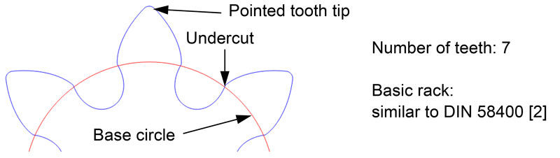
Step 1: specification of module and number of teeth.
Multiple calculations have shown that for the design optimized
here, the optimum number of teeth-per-pinion is 7.
Figure 3 shows a design similar to Figure 1, but with 7 teeth
on the pinion.
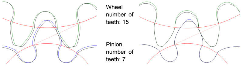
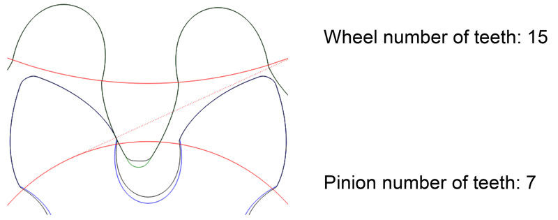
Figure 2 — Limited tooth depth with a small number of teeth; pointed tooth tip und undercut.Figure 3 — Pinion number of teeth — 7; conventional design — basic rack: similar to DIN 58400 (Ref. 2).Figure 4 — Left — complementary toothing; right — pinion addendum and wheel dedendum increased.Figure 5 — Pinion addendum and wheel dedendum increased.
The transverse contact ratio for the widest mesh is only
about 0.8. There is a mesh impact at the start of meshing. The
tooth depth on the pinion cannot be further increased due to
the tip limit.
Step 2:
increasing tooth depth by complementary toothing. Complementary toothing represents the state of
the art: the tooth thickness of the pinion is increased while maintaining an
unchanged tooth flank geometry and by counter-rotating the right and left tooth
flanks about the gearwheel center. The intermeshing gearwheel is changed
inversely (‘complementary’). These measures mean the teeth of the pinion are no
longer pointed; therefore the tooth depth can be increased.
Step 3: increasing the tooth depth by
accepting larger undercut. The tooth dedendum
of the pinion and the tooth addendum
of the wheel are increased; increasing of the
already present undercut is accepted.
Step 4: meshing optimization. At first sight
the resultant meshing appears unusual, but
definitely practical. Seen graphically, the
contact ratio over the tolerance range is not
optimal — but acceptable (Fig. 6).
By calculation for the widest tolerance situation,
a transverse contact ratio of approximately
0.9 results, which, while again not
optimal, is a significant improvement
compared with the conventional design
(Table 1).
Table 1 Comparison: calculated transverse contact ratio for the widest mesh
Basic rack
Calculated transverse contact ratio for the widest mesh
Conventional design according to Figure 1
Pinion 10 teeth, wheel 21 teeth
similar to
DIN 58400 [2]
Less than 0.6
Conventional design according to Figure 3
Pinion 7 teeth, wheel 15 teeth
similar to
DIN 58400 [2]
approx. 0.8
Increased tooth depth according to Figure 6 Pinion 7 teeth, wheel 15 teeth
special
approx. 0.9
The mesh as shown in Figure 6 still
exhibits weak points; if tooth flank wear
and pitch errors are considered, then, particularly
with narrow meshing, the result
may be a hard mesh impact or premature
contact.
Figure 6 — Increased tooth depth according to Figure 5 for narrowest, medium and widest mesh.
[advertisement]
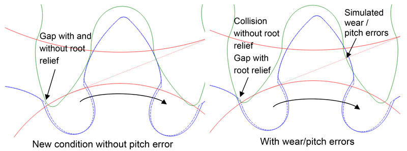
To prevent this collision the pinion is given root relief that,
in comparison with more usual root relief, primarily recesses
the dedendum in the area of the root surface or the undercut,
and mandatorily only removes a small element from the
involute form.
Figure 7 clarifies how this measure prevents a collision
before the desired meshing. However, a small part of the
involute form is lost, which further reduces the calculated
transverse contact ratio for the widest mesh. It is for this
reason that it is explained in the following which design and
mesh are to be favored.
Figure 7 — Pinion without root relief (dotted line) and with root relief (solid line) with narrowest tolerance situation.
Evaluation and Advantages of the
Optimized Design
With the optimized design, meshing takes place smoothly
and close to the pitch point. Very similar meshing conditions
exist over the entire tolerance range; the pinion involute is
shorter than that of the wheel. The whole involute of the pinion
engages throughout the entire tolerance range with the
wheel flank. The involute used by the wheel
lies more in the outer, middle or inner area of
the involute, dependent on the tolerance situation.
The start of meshing takes place over the
entire tolerance range below the wheel tooth
tip, which ensures a smooth meshing start.
Figure 8 shows that in the optimized design
the flank gap decreases in slower fashion and
the contact starts later (that is, closer to the
pitch point) than with the conventional design. Moreover,
with the conventional design there is a meshing impact
for the widest mesh because of the overly small transverse
contact ratio. With the optimized design the meshing start
is smooth, even for the widest mesh, with a transverse contact
ratio significantly less than 1. At the conventional design
pitch, error and wear can significantly amplify the mesh
impact, while with the optimized design the start of meshing
is indeed moved, but remains ‘smooth’ nevertheless.
Figure 8 — Start of meshing via tolerances: conventional design (Fig. 3, top 3 image rows) and optimized design according to Figure 7 with root
relief (bottom 3 image rows); pinion rotation angle between left and right image: 15°.
Figure 9 shows the calculated geometric transmission error
for the conventional and optimized design — without elastic
deformation and without pitch errors. The wide plateaus
represent areas in which the involutes are in contact. The
downward peaks are those areas between the involute
engagements. Therefore the width of the peaks is a measure
of how much the transverse contact ratio is less than 1.
Indeed, the transmission error (more accurately, the difference
between maximum and minimum values subsequently
referred to as Δ transmission error) for the narrowest and
medium mesh for the conventional design is approximately
zero; by contrast, the widest tolerance situation is equal to
a difference of about 4 µm. For the optimized design there
are similar curves for the transmission error for the three
tolerance situations. The difference between maximum and
minimum value is between 2.0 and 2.7 µm, dependent on
the tolerance situation. Moreover, the downward peak for
the conventional design for the widest mesh is narrower
than for the optimized design.
Figure 9 — Geometrically caused transmission error (calculated).Figure 10 — Problem in the calculated transverse contact ratio (e.g. — optimized design according to Fig. 7, mean tolerance).
Metaphorically speaking, the transmission error represents
for the conventional design a ‘narrow, deep pothole,’
while for the optimized design it represents a ‘wide, flat
depression.’
Although a transverse contact ratio greater than 1 over the
entire tolerance range is desirable, it is, however, not possible
with large tolerances relative to the component size. Also,
solely maximizing the transverse contact ratio is not appropriate.
Table 2 very clearly indicates for the widest mesh that
a smaller transverse contact ratio can even have a smaller
transmission error as a consequence.
Table 2 Comparison: computed transverse contact ratio and Δ transmission error
Conventional (Figure 3)
Optimized (Figure 7)
Narrowest mesh
Transverse contact ratio
1.0
0.77
Δ transmission error [µm]
0
2.0
Mean tolerance
Transverse contact ratio
0.95
0.74
Δ transmission error [µm]
˜ 0
2.3
Widest mesh
Transverse contact ratio
0.80
0.71
Δ transmission error [µm]
4.0
2.7
One reason the value of the computed transverse contact
ratio for such toothing systems is to be considered with caution
is that, as a result of undercut or root relief, there is from
a calculated viewpoint no contact in the area of the involute.
The difference between the actual contact and the involute
contact may, however, be in the sub-micrometer range,
i.e. — negligible in practice.
For evaluation of corresponding optimized toothing systems,
it is therefore suggested that less consideration be
given to the transverse contact ratio and that most attention
be paid to transmission error. Moreover, the mesh, especially
the start of the mesh, should be visually considered, which
in fact partially results in a somewhat subjective assessment.
Outlook
A design for microgears was presented that ensures uniform
operation over a wide tolerance range. Corresponding gears
were constructed and found to function well during internal
tests and customer trials. Viewed under the microscope,
the parts look like ‘actual gearwheels’ with tooth flank contours
that correspond to the figures shown. However when
the gearwheels are viewed with the naked eye, the question
nevertheless arises — to what extent optimizations in the micrometer
range on plastic parts remain solely of an academic
nature, and whether (to put it bluntly) triangular teeth with
rounded tip and root would not also serve the same purpose.
Experience has shown that small, plastic gearwheels are
in practice much more tolerant to deviations than would be
expected from pure theory.
In the sense of a proof of reliability for demanding medical
devices, the theoretical considerations are nevertheless not at
all in vain. There are very few standards dealing with microgears;
VDI 2731 (Ref. 1) cited at the beginning refers not for
nothing to Microgears: Basic Principles. Here the state of the
art and the differences relative to larger gears in respect to
design, production or measuring technology are presented.
‘It is intended to provide a basic repository of information,
to stimulate discussion, and, in the longer term, expansion,’
as explained in S ection 1 of VDI 2731 (Ref . 1). However,
etched-in-stone design guidelines for, example, basic racks
or tolerance values, are not included.
Miniaturization is just beginning.
References
VDI 2731, Part 1. Microgears: Basic Principles, Beuth Verlag GmbH,
Berlin, April 2009.
DIN 58400 (withdrawn without replacement). Basic Rack for Involute
Teeth of Cylindrical Gears for Fine Mechanics, Beuth Verlag GmbH,
Berlin, June 1984.
Jürgen Strüber has been a development
engineer at Bühler Motor GmbH since
March 2000, with a focus on calculating
gears and water pumps. He studied
(1995-2000) mechanical engineering
at Georg-Simon-Ohm Fachhochschule
Nürnberg (University of Applied Sciences,
now known as Technische Hochschule
Nürnberg Georg Simon Ohm). Strüber completed his diploma
thesis in 2000 at Bühler Motor on the simulation of the
creeping behavior of plastics.