[advertisement]

August 1, 2021


Design Applications Cement Food Packaging Steel Washdown Components Belts Chain Conveyor Drives Drives Gearboxes Gears Motors Speed Reducers Technical Articles Energy Efficiency Failure Force Life Materials Power Specification MRO Maintenance Repair Safety

Design Reviews - What to Review and When

Design Reviews—What to Review and When

Design reviews vary greatly by industry and regulatory requirements. We typically define them as Guidelines rather than Procedures, as this allows flexibility in their execution — both to skip over non-relevant sections and to dig deeper for those areas that go beyond the typical design and require closer examination. Having them as a “Procedure” can interfere with both of these variations. Our designs are mostly electro-mechanical- and motion control-oriented, so some of our checkoff list may not be needed in your application, while other whole areas may be required for your design reviews!

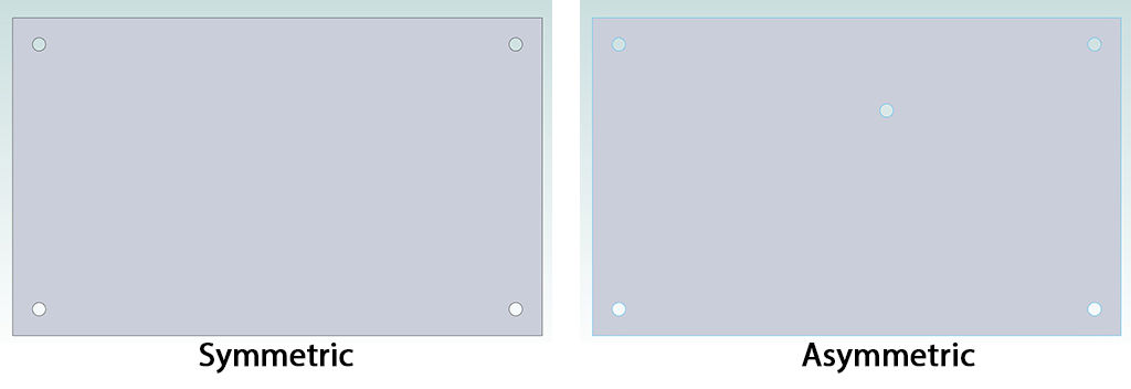
Here are what we cover in our typical design reviews. Some are trivial — did the title block get updated on all the sheets after a revision? Some are housekeeping — make sure the parts lists and fab drawings are updated from the final pass. Others pass on tribal wisdom, like asymmetric mounting of boards (see 4.5 below). Try to gain as much advantage when you do design reviews; they can result in greatly improved designs and can cut multiple iterations out of the process!

Design rules make it easy to make sure requirements are being met while the design is progressing.

Regulatory

  • 1.1 What requirements are specified for the system or subsystem?
    • 1.1.1 Are we following? Plans for agency approval?
  • 1.2 Is this a modification of an existing system that needs specific items to remain under existing compliances, and can those items remain unchanged?
    • 1.2.1 Submit any changes to certification agency for approval or testing.
  • 1.3 Are there specific procedures in place to avoid affecting critical sections of the design and critical components? Verify we are following them.
  • 1.4 Do internal and external agencies need to review the changes for continued compliance?
  • 1.5 Have all RoHS, Reach, etc. requirements been met with the components that have been selected? Have these been documented so they can be tracked. Back-ending this function is very difficult and may force a design turn!
Share and save:


This article appeared in the August 2021 issue.


Read PDF

[advertisement]

Housekeeping

  • 2.1 Verify title blocks, signatures, fabrication drawings
  • 2.2 Verify Design rules consistent with manufacturing, and with regulatory (i.e. trace spacings)
  • 2.3 Verify Parts list generated from current board revision and variation — check time/date stamps
  • 2.4 Only PDF version of drawings should be signed, not the source, as the signature needs application each time the drawing is changed; putting this in the word file or mechanical source ends up with the output being signed without the signatory having to be present to check!

Interfaces

Figure 3.5 shows differences in availability even from same manufacturer for the same basic part number. The middle two choices seem to have a lot more flow. You should check multiple distributors. Talking with a company rep may also gain insight.
  • 3.1 Verify Connector type and pinouts, orientation
  • 3.2 Verify I/O logic level compatibility, pullups, protection, especially for signals that interface externally.
  • 3.3 Verify protection of devices connecting across power domains for power timing issues; make sure driving an input will not back power sections not yet powered up as latch up may happen.
  • 3.4 Examine all signals crossing clock/time domains — are they re-clocked properly; are there asynchronous timing issues (metastability)?
  • 3.5 Verify footprints for all parts — sufficient for soldering, correct board density
    • 3.5.1 For parts available with multiple footprints, are we using the most commonly available variety? Are alternate sources actually available in that footprint?
    • 3.5.2 Especially for connectors — is there clearance for any tie down points, including brackets which to avoid shorting the surface traces below the connector. Is there sufficient hold down mechanical strength? Is there clearance for screw heads or nuts holding these parts down (if applicable).
  • 3.6 Do all footprints have a clear Pin 1 marker
  • Dot to upper right is pin 1. - This also shows a fiducial (middle marked with 17), and numbering of pins around the IC to help with troubleshooting and debugging.
  • 3.7 Do Diodes and LED and polarized capacitor have orientation clearly marked?
  • 3.8 Sufficient ESD protection for exposed signals (those not internal to board)?
  • 3.9 Is there a ground trace around exterior of board (if possible) to reduce induced ESD when picking up the board by the outside edges? This can significantly reduce stress on the board if a customer does not follow proper ESD ground strap procedures.
  • 3.10 Check for sufficient power ratings all resistors — 60% power rating, peak higher ok if duty-cycle limits heating.
  • 3.10.1 LED series resistors and opto-coupler series resistors are common offenders.
  • 3.11 Verify Capacitor voltage, material type, current rating. High-frequency circuits need appropriate dielectric!
  • 3.12 SPI bus — verify MOSI and MISO properly connected with respect to the controller!
  • 3.13 Verify any transient states that may occur while processor is coming up; make sure pullup and pull down resistors will handle the transition properly until the processor can configure the IO to controlled levels.
  • 3.14 Verify isolator outputs when only one side of the other is powered to make sure that power up transient power issues are avoided.
  • 3.15 Make sure all capacitive A/D converters are fed from a passive low pass filter to prevent accuracy and carry over issues.
  • 3.16 Are Programming pads available w/o disassembly (if possible)?
  • Pads for emulator tap are laid out on both top and bottom of board to make the connection accessible from either side of the processor board.
  • 3.17 Make sure to provide good ground pads for o-scope/logic analyzer for debugging.
  • 3.18 Bring out pads where possible of critical signals to vias with sufficient holes to hold scope probe. This may not be possible for very high-speed signals due to excess capacitance, but testing means should be determined early.
  • 3.19 Verify current rating of high current traces — wider traces needed on inner layers due to less cooling!
  • 3.20 Verify minimum and maximum holes and minimum anulus. For low-density boards .010 holes are less expensive than .008 if 008 not needed. Avoid smaller vias unless actually needed and you have processes in place to provide them at an acceptable cost.
  • 3.21 Prefer 1 oz (or less) on inner layers unless heavier copper is needed for current.
  • 3.22 Move high current traces to outer layers, if possible. (Sometimes using adjacent layers for counter flowing currents is needed to minimize EMI by reducing the loop area).
  • 3.23 Avoid discontinuities under very high-speed in ground planes under fast traces as these cause signal ringing and unwanted coupling. Stitch together to minimize altered paths if unavoidable. Avoid very high-speed signals as ringing can easily narrow the “eye” to where the board will not be reliable.
  • 3.24 Use thermals for through-hole connections to heavy traces or power planes.

Mechanical

This is two extrusion halves. The signal from the inside of the box (Right) does not have a direct path to exit the box. The long and thin clearance blocks all frequencies likely to be encountered, having a cutoff frequency much above the requirements (blocking all lower frequencies with a very high attenuation). A screw goes into the center hole to hold the two pieces together and to push the edges in contact. The clearance without the screw in place makes assembly easy.
  • 4.1 Check connectors (and other parts with metal) for areas that may short surface traces.
  • 4.2 Verify the mechanical dimensions including pads, plated through-hole requirements, and mounting holes; verify board with 3D!
  • 4.3 Verify needed screw lengths — use standard commonly available screw sizes and lengths. Do tolerance analysis to verify sufficient threads w/o exceeding allowed envelope over tolerances.
  • 4.4 Verify pads under screw heads for sufficient head/nut size, including hole diameter clearance which allows a screw to be off-center through-hole.
  • 4.5 Try to make mounting holes on PCB asymmetrical. This helps avoid strong vibration modes of the board. Nice symmetrical mounting holes make for strong vibrations when the wrong vibration frequency is found. An added screw off center can significantly spoil the “Q” of the vibration modes of the board. Think of a thumb on off center on a snare drum!
  • 4.6 Keep tall or sensitive components away from board edges and mounting holes. Locate and orient the long direction of SMT components (especially larger ones) so as to minimize mechanical stress when connectors are inserted, when the board is mounted, and when the board is depanelized.
  • 4.7 Verify pin 1 markings all components, K on diodes. Through-hole LEDs have square pad for anode (longer lead).
  • 4.8 Put a lead marker every 10 pins for large packages for easier debugging (when possible).
  • 4.9 Place fiducials for SMT well separated, with extra fiducial near high-density parts. Make sure fiducials will not be found if board is flipped or rotated so a misplaced board will fail looking for these before parts get placed wrong!
  • 4.10 Verify connectors in arrays will not overlap with other parts in the array nor with break apart lines.
A quick search of “vibrational modes of a rectangular membrane” will provide animations of the vibration modes. These require symmetry to allow the energy to easily propagate from one region to another. Break the symmetry, and the modes become much fewer and less effective.

Mechanical enclosure design

  • 5.1 Look over design for electrical noise consideration when choosing a RoHS electrical conversion coating versus anodization.
  • 5.2 Try to design overlaps to form “waveguide in cutoff” for joints to keep electrical noise from making it through a gap — either in or out of electronics.
  • 5.3 Make sure safety grounds are dedicated and masked (preferably electro-conversion plating); do not share the safety ground points with other mechanical functions unless you have regulatory signoff, as this is frequently not allowed.

General

  • 6.1 Design either with multiple source parts or with alternate parts, where possible.
  • 6.2 Look up configurations — what parts are stocked in quantity. Avoid those who few others are ordering. Look for parts available with multiple footprints, which are most in use and have multiple large-quantity alternate sources. Just because it is on the data sheet does not say they will be available!
  • 6.3 Mix capacitor sizes to avoid simultaneous resonances; a decade apart in bypass values helps suppress. Design to keep the loop area from ground plane to cap, and back to a minimum to minimize the inductance. This will extend the frequency coverage of the cap.
  • 6.4 Leave some spare footprints when possible — especially on new designs. Makes “blue” wiring much easier!
[advertisement]

Standard mechanical materials & machined parts

  • 7.1 Standard screw lengths, Phillips (or Allen head where needed), stainless for RoHS; MEPS reduce assembly time.
  • 7.2 Tolerance to guaranteed screw depth into threaded holes.
  • 7.3 Look at dimensions of standard raw materials; to get precise dimension use a light skin cut (for visible parts to have a nice look) on machined parts.
  • 7.4 Look at how the part is to be held in the vice on a mill and dimension from the fixed vice face and, typically, the left side of the part as it is held. Keep these same references when the part is rotated in other views on drawings.
  • 7.5 Try to take advantage of standard tool sizes for non-critical holes like vents. Plunge cuts are much less expensive than milled-shaped. Larger-diameter tools make for faster cutting: give a reasonable radius at corners so small tools are not needed (where possible).
  • 7.6 Have your machinist review the drawings early; many features can be easily altered for better manufacturability.
  • 7.7 For bent metal parts, the tolerance typically grows .010 for each bend (standard processing).
  • 7.8 Always work from the latest standard punch tool list for sheet metal parts; multiple hits are much less expensive than custom tools unless the quantity is very high.
  • 7.9 Dimension tolerances for what is actually needed: much of the cost is not in machining to .001, but in verifying the part to .001; if .010 is sufficient, don’t over-specify (but make sure the part will work with the tolerances given!)
  • 7.10 Make sure tolerances are shown between physical points that remain on the part, not off part conjunctions. Real places are much easier to measure when checking the part; projected points take special fixtures.

Donald Labriola P.E. is president at QuickSilver Controls, Inc. He has been working with step motors since high school, and has had these motors operating fieldoriented closed loop control since 1984.

Use both informal and formal design reviews. Early informal design reviews can set the tone early and save much work by helping with the philosophy and practicality. Formal reviews are needed to document and are another stage to eliminate issues before they surface in the field. If you find issues that slip through or were caught by careful attention in a design review, add them to the checklist you are using, i.e. — keep improving!

Know what the requirements are — even if you are specifying them yourself. Document these early; it is much faster to document as you are making these decisions than trying to reverse-engineer what you did! Make sure these created requirements are reviewed with the customer early in the design.

I would love to hear your suggestions for both electromechanical design and other areas of design!