The main drawback is that these integrated software packages are expensive to purchase and maintain and that they require extensive training and knowledge to ensure accurate results.
For motor design (magnetics), we started out with two parallel approaches that are still used today: the finite element software (FEA) which was introduced in the 1980s by Cedrat, Infolytica and A.O. Smith, and in-parallel macro modelers, which break down the magnetic circuit and iteratively solve simplified equations. SPEED software was widely popular and is used by several of our customers, and SPEED also has an integrated FEA option that allows for fine tuning of the magnetic curves, which can yield improved accuracy of the results.
In the past, we used SPEED software almost exclusively for our motor designs, and we found that the actual motor prototype delivered less efficiency than what the SPEED software had predicted, especially when designing high-rpm motors and those with low phase inductances even when we used the internal FEA module that SPEED offers to adjust the BH curves. When designing synchronous reluctance motors, SPEED appears to greatly overstate both the projected power output and efficiency.
We also noticed discrepancies in the projected motor efficiencies when using FEA software packages, especially when the excitation waveforms are generated via pulse width modulation (PWM). In many cases FEA-based design tools only describe the waveform, and they often rely on an AC analysis which allows solving the FEA much faster compared to a full transient analysis.
However, we have found it necessary to model the current waveform generation and its interaction with the motor magnetics in much greater detail and to perform a full transient analysis to accurately predict all the projected motor losses. We have found the use of broader system modeling tools, i.e., MATLAB, to be advantageous. They allow for us to easily and accurately model and co-simulate our control system and power switches, and we can also design the required control algorithms and automatically convert these into software for our embedded microcontrollers and digital signal processors.
Ever since we incorporated the accurate modeling of the PWM motor controller and excitation waveforms, we have been able to accurately predict the actual motor performance and, most importantly, its efficiency, which has been validated by testing over many motor designs. Thus, we consider co-simulation a key requirement for accurate motor design and performance prediction. Fortunately, most FEA and system analysis software packages offer a MATLAB interface to allow for easy co-simulation.
For the design of the power electronics, we use lower-level circuit analysis tools such as SPICE, giving us valuable insight into the inner workings of the controller and how we can efficiently drive the main power switches, which has become significantly more important as we are shifting from standard silicon-based technologies to wide-bandgap devices: silicon carbon (SiC) and gallium nitride (GaN). Furthermore, we are increasingly designing controllers that can operate in high ambient temperatures (up to 160°C/320°F) for military applications and for motor controllers integrated into the motor housing. Using these tools, we have developed our own driver stages that can switch wide-bandgap devices in the nanosecond range to design drives with almost 99% operating efficiency.
We can now use the co-simulation to solve very complex problems, such as magnetic bearing stabilization, acoustic noise control of electric motors and vibration-free propulsion, which involves integrating the electronic controls with the motor, the power electronics and the mechanical structure. Thus, we can be assured that the system will function as specified once we build the actual hardware.
In some cases, the use of this holistic approach also impacts design decisions. One such example was a traction drive with integral gears where a selection needed to be made between two different gear ratios: X and Y. There were some low-speed efficiency advantages for using ratio Y, but a full mechanical analysis revealed that ratio X would require less internal support and offer higher safety margins. Based on this analysis, ratio X was chosen. While such an analysis is not inherently novel, the use of an integrated analysis tool suite allowed us to construct and optimize a single model and simultaneously gain all the relevant information about magnetic performance, thermal management, critical frequencies and the mechanical strength. Any optimizations could be made quickly and simultaneously using a single model to obtain the desired magnetic performance, weight reduction and optimized cooling channels while assuring strength and thermal management. In the past, the model may have been bounced back and forth between different engineers, which would add significant amounts of design time and expenses.
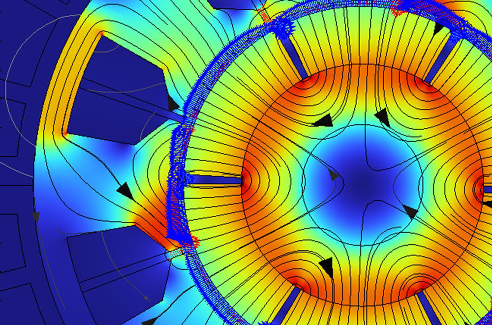
Below we will give some examples of data obtained for a series of different analyses. One important aspect is the accuracy of modern FEA analysis. In Figure 1 we show the comparison of a static torque curve that was obtained from two different FEA software packages and how closely the results from the different software packages match.
 Figure 1 Comparison of static torque curves from two different FEA softwares.