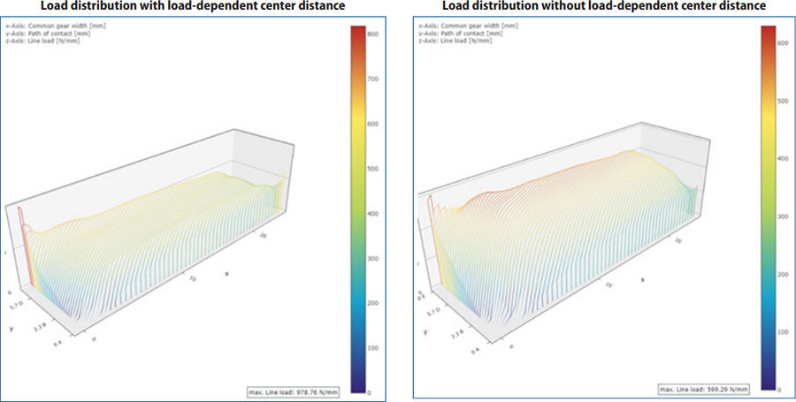
The microgeometry of the gear plays a key role in the load and pressure distribution. Figure 2 clearly shows that the gear was designed without taking the influence of the load-dependent center distance into account. If this influence is considered, the load distribution in the direction of the mesh is no longer uniform, but increases significantly.
Figure 2: Representation of the load distribution with and without the load-dependent center distance from an FVA-Workbench output report.
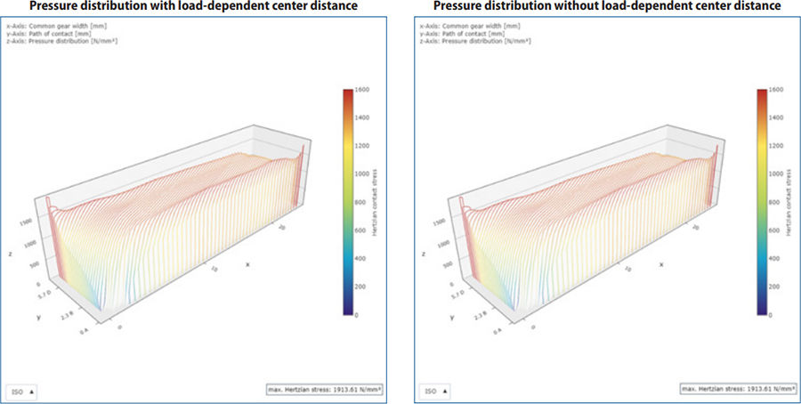
Figure 3 shows a simulation of the pressure distribution from an FVA-Workbench results report. Excess pressure can be seen at both the beginning and end of the mesh due to insufficient tip and root relief.
Figure 3: Representation of the pressure distribution with and without the load-dependent center distance from an FVA-Workbench output report.
Influence on the noise excitation
One evaluation criterion for the noise excitation is the transmission error and excitation level. Transmission error occurs as a result of fluctuating stiffnesses in the gear and different loads, depending on the mesh position. The excitation level is formed from a weighted sum of the individual frequencies of the gear, with an emphasis on the audible frequencies. This is described in FVA 133 — Overlap ratio, FZG — TU M¼nchen.
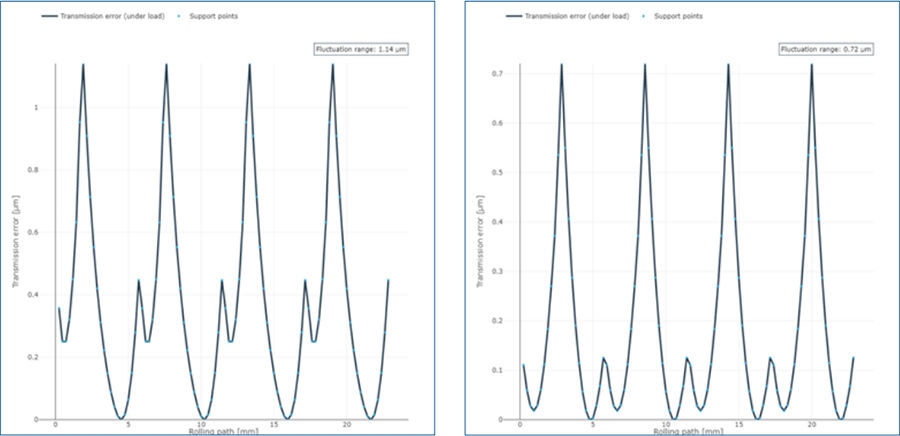
The influence of the load-dependent center distance becomes even clearer if the transmission error is calculated from the represented load distribution. The range of variation of the transmission error increases by more than 50%, while the excitation range increases from 16.79 dB to 19.35 dB. It can therefore be assumed that this gearbox is significantly louder than one in which the load-dependent center distance is considered in the design.
Figure 4 shows a simulation of the transmission error with and without the load-dependent center distance from an FVA-Workbench results report.
Figure 4: Representation of the transmission error with and without the load-dependent center distance from an FVA-Workbench results report.
Influence on the tooth root stress
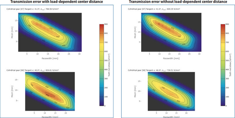
FVA 264 offers a method for further consideration of the tooth root stress, in which the local tooth root stress over the mesh can be solved using the BEM method. Figure 5 shows a simulation of the tooth root stress with and without the load-dependent center distance from an FVA-Workbench results report.
Figure 5: Simulation of the different tooth root stress with and without the load-dependent center distance from an FVA-Workbench results report. The opinion is shown in each image.
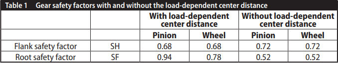
Analysis shows that the tooth root stress on the wheel increases from 739 N/mm2 to 826 N/mm2 when the load-dependent center distance is taken into account. At the same time, the stress on the pinion decreases slightly from 809 N/mm2 to 788 N/mm2.
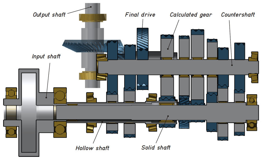
Consideration of the load-dependent center distance in the FVA-Workbench
This example features a particularly soft design. As a result, the influence of the load-dependent center distance is very prominent. In particular, a significant increase in the tooth root safety can be observed. However, this is not a general trend; it only applies to this example. Therefore, consideration of the load-dependent center distance is always recommended.
 M. Sc. Benjamin Abert is Head of Consulting & Service, FVA GmbH. He studied at the TU Clausthal, and began work in 2013 at FVA-GmbH as calculation expert for plain and rolling bearings. Since 2018 he has been responsible for expert support and sales.
Considering the local flank parameters, such as pressure or transmission error, a significant influence of the load-dependent center distance can be observed. Pressure increases of around 400 N/mm² can be seen at the transition between the tip relief and the flank. This shows that the influence of the load-dependent center distance must be taken into account when designing modifications. The noise excitation of the gearbox can be evaluated from the transmission error. The more than 50% increase in the transmission error underscores the necessity of accounting for the load-dependent center distance. In this case, it becomes clear that the applied modification is no longer adequate. With the FVA-Workbench, the load-dependent center distance is always considered.