Regardless of whether a design is sequential or not, there also exists the phasing between the sun/planet (S/P) to the planet/ring (P/R), which can themselves be either in or out of phase.
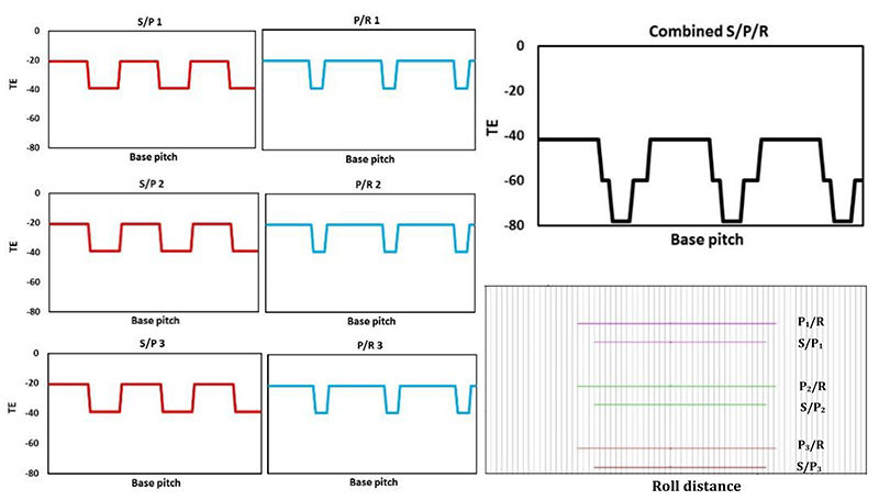
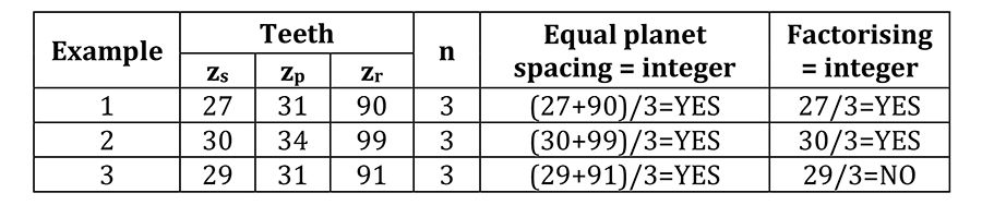
The notion of phasing is investigated using commercially available gear analysis software (Dontyne) (Ref. 11) which adopts simple strip theory (Ref. 12) to establish the quasi-static TE. Here, tooth stiffness is assumed parabolic and a maximum at the pitch point, falling to approximately 70% at the start and end of active profile (Ref. 13). Combined with load sharing, micro geometry corrections and misalignments, the total expected quasi-static TE can thus be established. Using an iterative approach, the analysis also accounts for unequal load sharing amongst the planets due to differences in the instantaneous mesh stiffness between out-of-phase planets. An arbitrary example illustrating the effects of phasing is presented in Figures 1 through 3, for factorizing and non-factorizing designs, with ‘n’ planets, and sun, planet and ring tooth numbers of zs, zp and zr respectively. For simplicity, each planet experiences equal load with a constant mesh stiffness, the details of which are presented in Table 1. Here, without presenting the specific details of load or geometry, the magnitude of the TE is irrelevant, and the example is merely presented to provide the reader with a greater understanding of planetary phasing, and the potential reduction in TE with only slight modifications to tooth numbers.
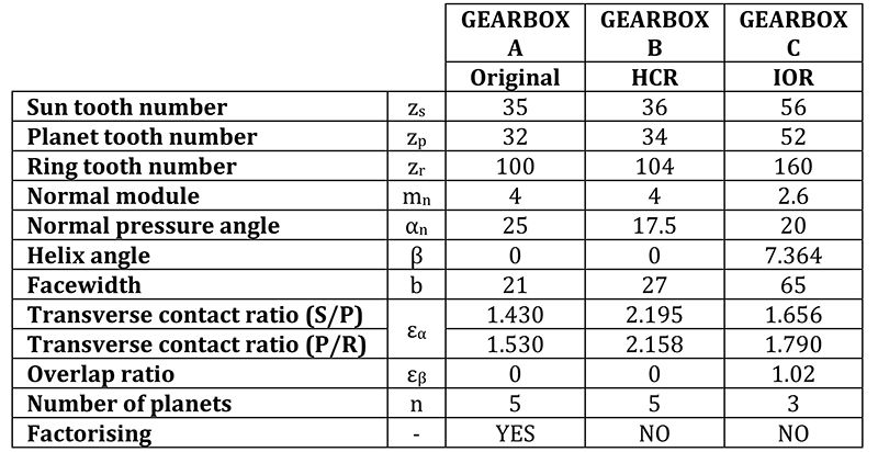
Table 1: Tooth numbers for factorizinf and non-factorizing designs
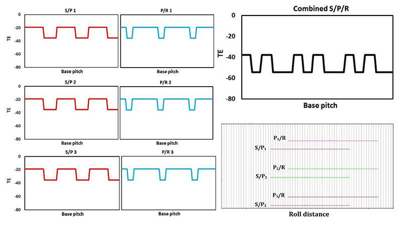
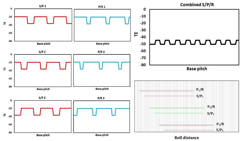
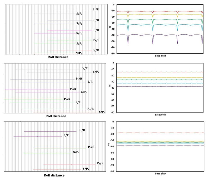
Example 1 is factorizing, such that the phasing of all S/P are identical. Likewise, the phasing of all P/R are identical, as illustrated in Figure 1. Note however, regardless of the factorization, the length of the path of contact of the S/P is less than that of the P/R, as illustrated in the phasing diagram Figure 1, whereby the P/R engage and exit mesh before and after the S/P respectively. In this example, the total combined TE is a direct combination of the S/P and P/R. Example 2 is still factorizing, however there is a distinct shift in the phasing of the S/P with that of the P/R as illustrated in Figure 2. As a consequence, when the TE of the S/P is combined with that of the P/R, the total TE (17 μm) is significantly less than that presented in example 1 (37 μm). Finally, example 3 adopts a non-factorizing design such that the phasing of all the S/P are different, as are the P/R. As a consequence, the total TE has been reduced to only 6 μm, as illustrated in Figure 3.
Macro Geometry Design
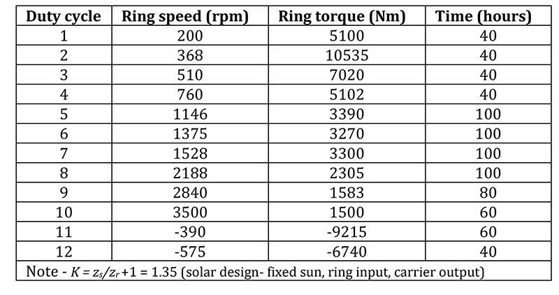
The objective of this research was to utilize the theory of phasing to optimize an existing epicyclic gearbox to produce the lowest TE, whilst understanding the resulting implications with regards to the complexity, cost, weight and possible risks. To facilitate this, an initial design and detailed specification was required, whereby a load spectrum, together with a required ratio and epicyclic arrangement fully defined the system, as detailed in Table 2. Each design was analyzed in the first instance for strength, in accordance with ISO 6336:2006, then optimized by analyzing the elastic mesh deflections such that the transmission error was further minimized using micro geometry corrections. In addition to the optimization process, each gearbox was fully designed and detailed, including housings, carriers, shafts, bearings, splines and the lubrication delivery system, only after which can the true benefits and implications of each design be fully understood.
Gearbox A. The base design was an existing spur gear system with 5 planets, and sun, planet and ring tooth numbers of zs = 35 zp = 32 and zr = 100 respectively, such that the planets were equally spaced and factorizing.
Gearbox B. With only slight modifications to the tooth numbers specified in Gearbox A, and a small change in the gear ratio, the macro geometry was modified such that it was now non-factorizing by adopting sun, planet and ring tooth numbers of zs = 36 zp = 34 and zr = 104 respectively, while maintaining equal planet spacing and the use of 5 planets. The basic rack profile and pressure angles were modified such that a transverse contact ratio greater than 2 was achieved, resulting in an HCR design.
Table 3: Elimination of torsional and transverses modes
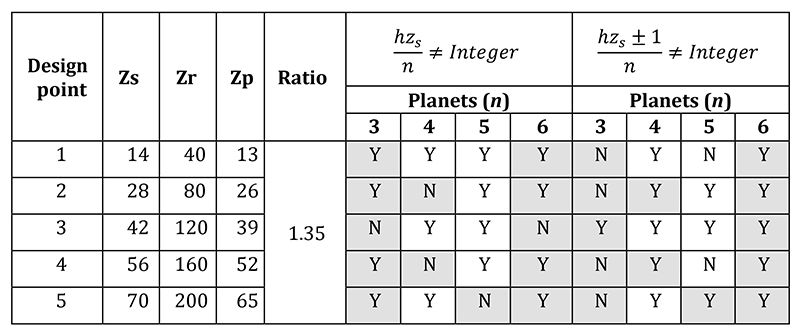
Gearbox C. Gearbox C adopted helical gears, with an integer overlap ratio slightly larger than 1. Table 3 presents a list of viable tooth numbers, without addendum modification, which satisfied the required gear ratio, equal planet spacing, and the potential to eliminate torsional and transverse modes of excitation, based on equations 1 and 2 respectively, analogous to that previously presented by Palmer and Fuehrer (Ref. 2), for the first harmonic (h). Equal planet spacing is represented by the shaded cells in Table 3.
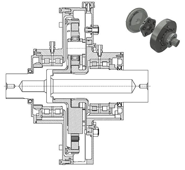
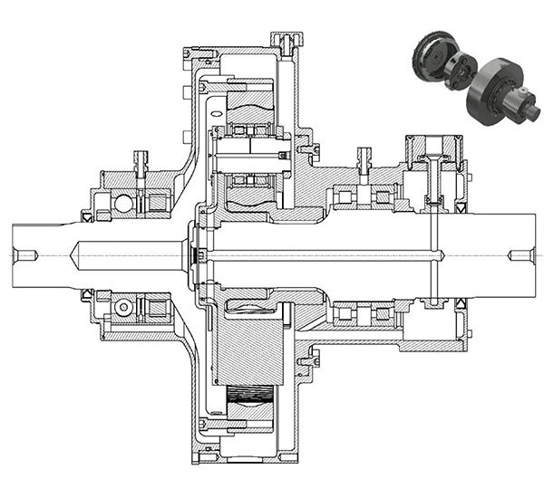
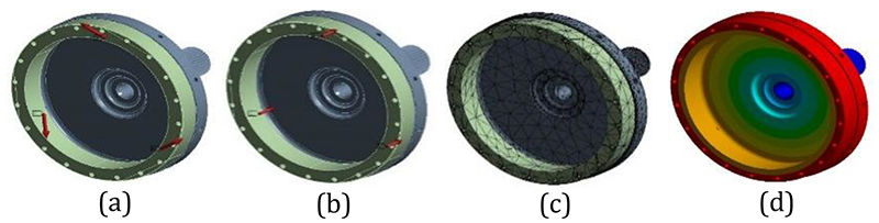
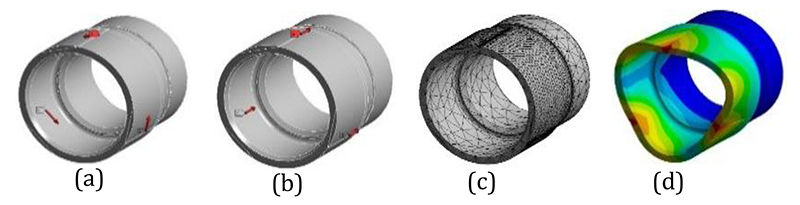
Taking into consideration cost, weight, planet load sharing factors, shaft sizing and bearing loads, design point 4, with 3 planets, was considered a good compromise based on gear diameter and module and gave a balanced design with regards to contact and bending safety factors. Furthermore, it provided a sequential design with equal planet spacing, albeit at the expense of potential transverse vibrations. The final macro gear geometry chosen for all three gearboxes, A, B and C, is presented in Table 4. Detailed gear stress analysis for both new designs (B and C) was conducted in accordance with ISO 6336:2006, using the load spectrum presented in Table 2, ensuring each proposed design provided minimum contact and bending fatigue safety factors of 1.0 and 1.4 respectively. Each design adopts a suitable planet load sharing factor determined in accordance with AGMA 6123-B06, depending on planet numbers and system flexibility. The remaining mechanical design of both Gearbox B and C was conducted in accordance with 1) AGMA 6001-E08 for shaft stressing, 2) ISO 281 2007 for advanced bearing life, 3) DIN 5480:2006 for spline geometry, and 4) SAE M-117 for spline stress analysis, the results of which are illustrated in Figure 4 and 5.
Table 4: Gearbox A, B and C geometry specification
Figure 4 Gearbox B, HCR spur design.
Figure 5 Gearbox C, IOR helical design
Micro Geometry Design


 Power Transmission Engineering is THE magazine of mechanical components. PTE is written for engineers and maintenance pros who specify, purchase and use gears, gear drives, bearings, motors, couplings, clutches, lubrication, seals and all other types of mechanical power transmission and motion control components.