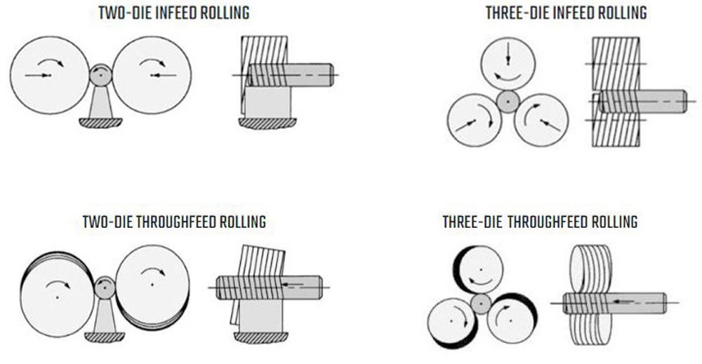
Throughfeed is used to roll continuous lengths of thread using relatively narrow dies tilted on opposite skewed axes. The blank rotates and feeds through two or three dies at fixed center distance while the form is progressively generated as it travels through the dies. Throughfeed rolling of long forms having lengths of four meters (12 feet) or more can produce rolled product at rates of 30 to 60 inches per minute or more depending on the capability of the thread rolling machine and design of the dies. Forms that are rolled in long lengths can be colletted in a screw machine and cut into shorter pieces for subsequent machining or finishing operations.
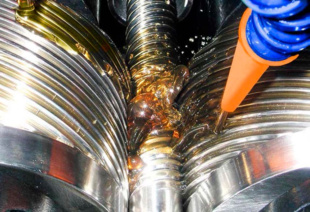 Figure 5—Throughfeed lead screw rolling.
In a cutting operation you’re limited by the power of the machine tool, the length-to-diameter ratio of the part with respect to form depth, and the ability to remove heat at the cutting insert. In a cold rolling operation, you’re limited by the power of the rolling machine and the ability to transfer the electro-mechanical energy into forming the threads without slipping or stalling the blank. The unbalanced cutting forces of a single-point cutting operation can severely limit the length of form to be cut based on the length-to-diameter ratio and form depth. Rolling has balanced forces around the part which essentially allows you to produce unlimited lengths if the parts can be sufficiently supported.
Excellent Surface Finish
The conjugate interaction of the dies and the part during a rolling operation is like a transmission gear mesh. The outside diameter of the die continuously forms the root diameter of the part which forces material to flow along the die flanks into the die root diameter. The die root diameter forms the major diameter of the part. This meshing relationship forces the velocity ratio of the dies and part to achieve equilibrium. However, since there is continuous uninterrupted contact between the die and part transitioning from part root to crest, this means there is only one theoretical diameter of matched angular velocity. Above and below this zero-slip diameter, which usually occurs around the pitch line, there is a differential of angular velocity. The differential results in a sliding and burnishing action on the surface of the rolled part. This means excellent surface finish is achieved directly from the forming operation without the chatter marks of a cutting tool.
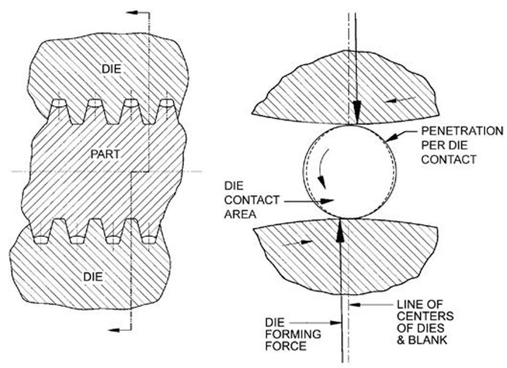 Figure 6—Die and part conjugate relationship.
Finishes superior to that of grinding in the range of .020 μm to .100 μm (2 μin to 4 μin) Ra can be achieved by rolling operations. Smooth finish also means improved wear resistance and high efficiency in rolling and sliding contact, especially in the direction of the helix. These characteristics are very important for the performance of lead screws, ball screws, and other similar actuator screws which must interact with a mating bearing component.
Figure 7—Surface finish achieved by rolling operation.
Improved Fatigue Strength
Rolling can be considered a continuous but intermittent rotary forging process. A single point on the blank contacts each die once per revolution of the blank following an epicycloidal path. The radial velocity of the point goes to zero at the point of contact with the die like the converging behavior of a hammer forge. The result is a forged part structure with uninterrupted grain flow lines that follow the geometry of the rolled form. Compressive residual stresses in the root area of the thread combined with the uninterrupted grain flow and smooth surface finish help retard crack initiation and propagation under cyclic loading conditions.
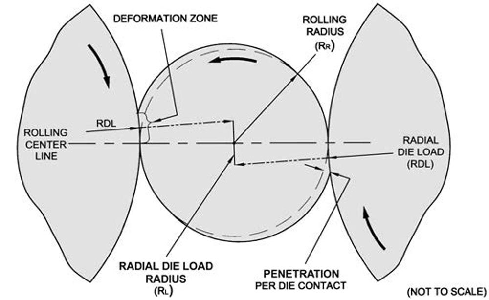
Figure 8—Two-die rolling system diagram.Strain hardening that occurs due to cold working of the material is another mechanism to be considered with respect to overall strength. Alloy steels and stainless steels which work-harden when cold worked, can strain-harden as much as 5 to 8 HRC points or more during the rolling operation. It is not uncommon for a rolled thread to be in the vicinity of 10 to 20 percent stronger than a cut thread of the same size in a given material. A cutting process removes portions of the existing material structure and does not yield beneficial residual stresses in the form. It can also leave sharp transitions whereas rolling leaves radius transitions which minimize stress risers.
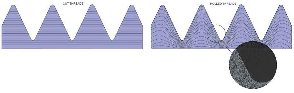 Figure 9—Cut thread grain flow vs. roll thread grain flow.
Rolling can also be carried out in heat-treated materials which can result in additional fatigue resistance. This can be a showstopper for cutting processes where machine stiffness and cutting edges don’t hold up. However, high hardness blanks significantly reduce the tool life of a thread rolling die and significantly increase forming loads. Rolling is regularly carried out on pre-roll blanks with hardness of up to 36 HRC, and higher. Above this level of hardness, the tool life is significantly reduced. Some high-strength threaded studs, bolts, and actuator screws require rolling to be performed on blanks up to and exceeding 46 HRC.
Precision Tolerances & Dimensional Repeatability
Achievable tolerances and dimensional repeatability are governed by the accuracy of the die form, type of rolling process used, accuracy and stiffness of the rolling machine, and quality of the pre-roll blanks.
The final form geometry of a rolling die is precision ground, typically after the die steel has been heat treated. This minimizes the risk of distortions that could occur in the die threads during the hardening process. The high accuracy ground form geometry is then replicated in the blank during the rolling process.
A thread rolling die does not typically wear like a standard form-cutting tool and thus does not require continuous compensation over its life. Rolling dies tend to last a long time with very little wear before they begin to fail. This means a single rolling machine size setting is often required to produce precise and repeatable rolled forms until complete die failure occurs. Localized die wear is not usually the cause for changing the dies because remaining good sections of the die will calibrate the final rolled form until the entire die surface has failed.
The rolling machine directly controls the workpiece pitch and root diameters by precisely positioning the dies at the appropriate center distance. The diameter of the pre-roll blank controls the level of fullness of the final major diameter and whether there is a closed or open seam at the thread crest. However, once the dies are filled completely, the major diameter is directly controlled by the dies, and the elastic stiffness of the rolling machine will inhibit the dies from penetrating any further. Precision CNC thread rolling machinery can hold part to part diameter variation of .005 to .008 mm (.0002 to .0003 in.) with tightly controlled blanks.
With infeed rolling of shorter length parts, all the form characteristics including the lead accuracy follow the geometry of the die. Most materials that are good for rolling have negligible elastic spring-back after infeed rolling and thus don’t require any special compensations of the die form or die lead. Precision CNC thread rolling machinery and infeed dies can hold part to part lead variation within .002 mm per 25 mm (.00008 in. per inch) rolled length with tightly controlled blanks.
Throughfeed rolling, which is primarily used for producing long lead screw and actuator screws of four meters (12 ft.) and longer involves more variables when it comes to characteristics such as lead tolerances. The rolled form length is considerably longer than the working face of the die and lead error becomes cumulative. There tends to be some axial flow of material during throughfeed rolling as the penetrating ribs of the die simultaneously feed the part. Resulting internal residual stresses cause axial spring-back of the part which results in a lead which is shorter than the lead of the die. This condition is more pronounced when the form depth is 15 to 25 percent or more of the part diameter and when the root profile of the part has a relatively wide flat.
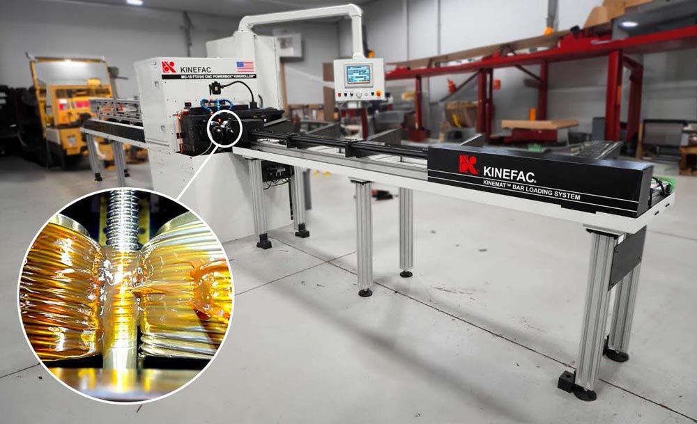 Figure 10—Kinefac MC-15 CNC KineRoller with bar feed unit.
Thermal characteristics of the throughfeed process also contribute to the amount of die lead compensation. The energy required to roll is transferred into the part and comes out as heat. Part shrinkage due to cooling to room temperature can also result in a lead which is shorter than the dies.
Spring-back compensation for lead accuracy is generally determined by testing due to the multitude of variables involved. Once determined, it will remain constant and repeatable assuming good consistency of the blanks. Precision CNC rolling equipment and throughfeed dies with good blanks and thermal stabilization of the rolling lubrication and dies can produce ball screw, trapezoidal screw, and ACME screw lead accuracy of .025 to .050 mm per 300 mm (.001 in. to .002 in. per ft.) rolled length. Meeting a tolerance of .100 mm to .150 mm per 300 mm (.004 in. to .006 in. per ft.) is standard. A good thread cutting or grinding machine with an accurate lead screw and high stiffness slides can also achieve precision lead tolerances.
Material Savings & Reduced Waste
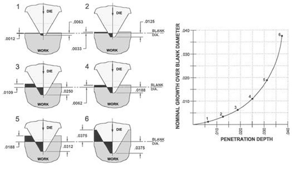
Thread and form rolling is a constant volume process, meaning material is neither added nor removed. Therefore, the volume of the pre-roll blank is the same volume as the final rolled part. The pre-roll blank diameter is smaller than the major diameter of the rolled form and is usually close to the pitch diameter. This is because material is displaced radially from the blank into the die form during penetration. The angled flanks of the die thread form provide a wedge-action to raise the material above the blank surface as the dies are penetrating. A cut thread must start out with a blank which is at least at the major diameter because material is removed to leave the desired form. A calculation by volume can demonstrate a potential material savings of close to 20% or more when using the rolling process.
Example: Throughfeed Rolling 1-1/4"-5 TPI ACME Lead Screw
Pre-Cutting Blank Diameter ~1.250-in. (31.75 mm)
Pre-Roll Blank Diameter ~1.132-in. (28.75 mm)

Another key benefit of rolling is the elimination of waste. Rolling could be considered a green manufacturing process since it is displacing material from one location to another on the same blank without creating waste. This is unlike a cutting or grinding process which generates chips or swarf that must be disposed of.
Material & Form Geometry Considerations
Most low-carbon steels such as 1018 and 1020, medium-carbon steels such as 1045 and 1050, alloy steels such as 4140 and 4340, and stainless steels such as 303 and 304 are good for rolling. Non-ferrous materials such as copper and aluminum can also be rolled. Alloying with elements such as nickel or chromium can increase the effects of work-hardening during cold work and should be considered for tool life.
Softer materials have more of a tendency to form a seam at the crest of the rolled part than harder materials. The seam is a mechanical closure of material due to metal flow behavior along the die flanks in the rolling process. Seams are generally very shallow and have no effect on the strength or performance of the rolled form. The seam can be closed completely for visual purposes, but it does mean the rolling dies are filled completely and can result in reduced tool life.
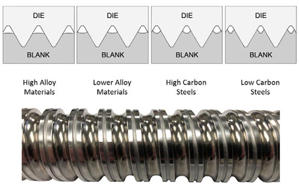
Figure 11—Material seaming behavior with rolling ball screw example.
Thread form geometry also influences the performance of the rolling process and tool life. Rolled forms are ideally designed with sufficient corner radii to help promote material flow and reduce stress risers. Flank angles and pressure angles are ideally kept above a low of 10° to 12° and lead angles are ideally kept under 30°. Form depths should be kept under 25% of the part major diameter, and tooth thickness versus tooth space should be as balanced as possible.
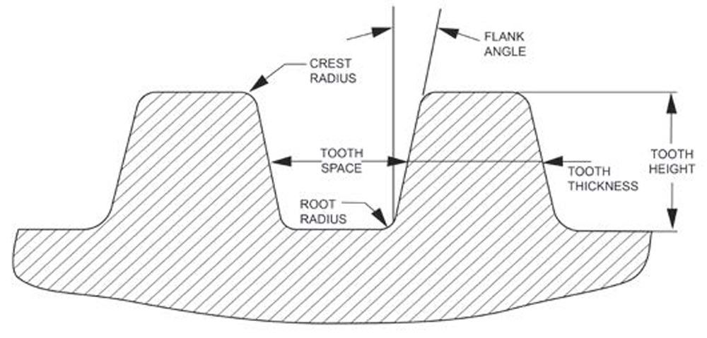 Figure 12—Form profile geometry.
The rolling process has been applied to parts as small as .25 mm (.010-in.) in diameter to over 150 mm (6 in.) in diameter. Size and length are limited by rolling machine tonnage, power, and die size capacities. Forming loads of over 330-tons are possible on large CNC thread rolling equipment.
Summary
Cylindrical die thread and form rolling is an ideal process for producing high accuracy lead screw and actuator screw components with many benefits. To learn more about what can be rolled and how to apply the rolling process to your precision lead screw and power transmission products - including splines, knurls, and serrations, visit kinefac.com or email sales@kinefac.com.
References
1. Rolling Process. H. Greis, N. Greis, C. Garniewicz, D. Willens. McGraw Hill Manufacturing Engineering Handbook (Geng) Second Edition. (2015). 26-1 - 26-27.
2. Roll It. H. Greis. Cutting Tool Engineering. (DEC 2004). 49-54.
3. As the Worm Turns. H. Greis. Gear Solutions. (JULY 2004). 30-35.
4. Six Common Myths of Thread Rolling. D. Willens. Fastener Technology International. (AUG 2018). 70-76.
5. Let’s Roll. D. Willens. Cutting Tool Engineering. (AUG 2019). 26-35.
6. Kinefac Strategy on Rolling Up a Fortune. H. Greis. Metalworking News (DEC 1968).
7. Thread and Form Rolling; History and Development. Reed Rolled Thread Die Co. Handbook. (SEPT 1961). 4-5.
8. Kinefac Corporation at www.kinefac.com