Torque Generation
The step motor only generates torque when there is a an error angle present. Zero error (difference between the magnetic angle presented to the motor via the two motor phase currents and the mechanical angle of the shaft). The electrical cycle repeats every 4 full steps (7.2 mechanical degrees for a 1.8 degree stepper). If the rotor is slightly ahead of the magnetic angle, then a negative torque is generated (Figure 4 shows normalized torque versus error angle in steps). A negative error angle produces a positive torque - as long as the error is less than 2 steps. The maximum torque generated is at one full step error and going beyond plus or minus 1 full step of error and the torque starts falling. Going past 2 full steps and the torque pushes the rotor further away until it comes to a rest again at 4 full steps (or a multiple of 4 full steps) from the targeted position. This is how open loop step motors loose steps.
Of note is that a load requiring 50% of the motor torque forces an error of 30 electrical degrees or 1/3 of a full step. Friction is only overcome if the error angle is sufficient to generate torque sufficient to exceed the friction magnitude. Any ringing may end up on either side of the zero point according to which side of the ringing waveform ended up with just enough friction to “capture” the rotor and stop motion. So micro-step drives, even if there are many fine divisions very accurately controlled, still may have significant following and stopping error due to load forces and friction.
True servo closed loop systems measure the error and apply appropriate current at the needed angle to move the rotor to the desired position. Quasi-closed loop steppers only prevent losing multiple steps, but otherwise still have the problems with load and friction induced errors.
Resonances
Low frequency resonance arises from the torque curve of the motor (which approximates a K-theta rotary spring) interacting with the rotary inertia of the motor (and the load). This sets up a rotary pendulum. When the stepping frequency of the motor excites the resonance of this pendulum, it causes an oscillation to grow. At some frequencies, the motor ends up moving in the wrong direction as the next step is applied, resulting in 90% or more loss in available torque and very rough motion. Lost steps or total loss of synchronization may happen if the load torque exceeds the available torque. It is also possible to excide other modes where the motor operates at a fraction or a multiple of the drive frequency due to the non-linear torque curve causing non-linear mixing of the applied sine wave with the back-EMF of the motor. You may get motion but at the wrong speed or the wrong direction!
The low frequency resonance issues are still present with quasi-closed loop (error limiting systems), except that they will not lose steps. True closed loop system keep the motor phase angle at either +1 step or -1 step and vary the current magnitude to get the required torque. By keeping the motor at the peak of the torque curve, the motor efficiency is maximized, while also making the derivative of torque with respect to angle zero. The system is no longer a 2nd order oscillatory system, but rather a damped first order system: the motor runs cooler and smoother!
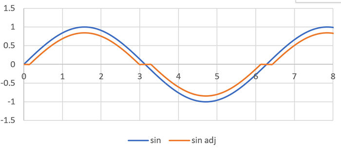
Mid-frequency resonance is not a true resonance, but rather a limit cycle oscillation. When using a peak current controlling recirculating drive, there is a critical frequency where there is not quite enough on time for the controller to bring the current to the desired level in the provided time. The back-EMF of the motor and the motor inductance resist the rate of current change needed. At this speed, the drive is no longer able to reach the full current, and so the drive switches from acting like a current controlled drive with a low phase lag to being a voltage driving the inductance of the motor with a 90 degree electrical lag. The reduced drive angle causes the motor to slow down slightly, which then allows the current control to engage, only to speed up and no longer reach full current. The resulting instability due to alternating between a current control and voltage control causes a speed oscillation that appears to be a resonance. Closed loop control of the motor current using a knowledge of this issue is able to suppress this limit cycle allowing for a wide range of speeds with full available torque and significantly smoother motions.
High Inertias Interacting with Low Damping Current Drives
Dynamic errors can be very problematic with high inertia loads. Even with careful ramp generation to attempt to minimize the ringing, a load can oscillate about the commanded trajectory by ±½ step over the duration of even an extended move. For example, this type of oscillation has been noted to continue almost unabated over a 16 second spin of a high inertial load. The oscillation remained over the full spin time and likely would have continued if the duration of the spin had been longer. This continued oscillation is due to the very low damping associated with a current mode driver interacting with a step motor.
Additional errors can occur if the motor is operated near resonant frequencies of the motor. Avoiding resonance involves trying to jump through the problematic resonance frequencies to keep from building up oscillations, but that may not be the motion needed for the apparatus!
Many microstep controllers also have a problem at higher speeds as they cannot update the requested phase fast enough to hit all 256 micro-steps of a high-resolution microstep controller. They end up having to change modes at different speeds which can give rise to torque hiccups at these transitions. The chopping rate may also not allow the driver to actually hit the intervening micro-steps as the chopper drive may not be in the drive mode for several of the intervals when chopping at a nominal 25kHz to avoid excess heating.
The inherent damping of a step motor with a low impedance drive can be easily seen by shorting the leads of the step motor and attempting to rotate the shaft. A true current mode driver has a very high impedance which can impart torque, but does not interact significantly with the motor back-EMF. A controlled impedance drive algorithm can provide good 4 quadrant performance, high efficiency, and significant damping to allow for very smooth operations even with a widely varying load.
The ultimate performance of these motor varies greatly with the drive and control algorithms and circuits. Motor efficiency, acoustical noise, vibration, damping and available torque-speed curves can all be significantly improved by the appropriate algorithms!