Shrink Your Start-to-Finish Time
Boosting Productivity in Gearbox Design with Siemens Digital
An increasing awareness of environmental concerns has given rise in the automotive industry to more stringent energy efficiency and emissions targets. However, these new targets make it challenging for manufacturers to balance customer expectations for higher performance with regulatory requirements. The mechanical transmission has been the focus of many auto maker’s strategy for achieving the new efficiency standards, because improperly tuned transmissions can waste as much as eight percent of the rotational energy from the output shaft into heat and vibration.Cutting these losses in half could potentially save 9.3 million tons of CO2 in the automotive sector alone, according to recent research studies1, 2. Unfortunately, these studies do not account for loss phenomena and their impact on performance attributes like durability and noise. Finding a viable balance of component performance and efficiency will require predictive capabilities with respect to system-level dynamics within the transmission design engineering process. While transmissions and gear boxes are most closely associated with internal combustion engines, durability and performance efficiencies may push electric vehicle manufacturers to adopt two or three gear transmissions to account for different driving conditions and further increase range.
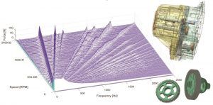
Until recently, building a full transmission model in a multibody simulation tool was a tedious and error-prone process done by hand. Modeling, parameterization and iterations to build fairly complex models could take up to multiple days for an experienced user. Fortunately, that is no longer the case. The model gearbox including geometry in the image above was produced in just minutes with a new class of multibody simulation tools.
This new approach offers an easy-to-use interface to build complex transmission systems. The user begins with the transmission layout setup, arranging the shafts, gears, bearings, etc., and defining the gear meshing conditions for spur, helical and planetary gear systems. Once completed, an ISO 21771 standard compliant gear geometry calculation can be performed, generating the gear geometry from the design parameters according to the standard. Gear microgeometry can also be automatically generated at this stage to include profile and flank line modification or combination thereof, along with a gear contact model input file.
After applying boundary conditions such as initial angles, automatic gear phasing, joints (bearings and couplings) and any other constraints, the gear contact model is interfaced such that the user is ready to solve the transmission system—typically in less than an hour.
Solving the transmission system
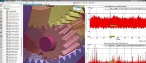
There are three main goals in solving the gear contact model; detecting the contacts, computing the required deflections and translating those deflections into loads on the system. These gear contact forces are accurately applied by the multibody solver to calculate the system level loads, an extremely important factor in predicting noise, vibration and harshness (NVH) behavior and durability. The most important of these geometrical effects, dynamically captured by the new gear contact element, can be seen in Figure 2. All of these effects are captured in a single suite of simulation capabilities in the new Simcenter 3D Motion Drivetrain transmission builder to solve the gear contact model.

Standard method
This method is intended for systems where global behavior of the drivetrain is important, stiffness is constrained and computed through ISO formulas3. Though only producing a qualitative approximation of the true stiffness of the analyzed gear pair, the standard method is of high value for resonance analysis and preliminary design revisions. Adding contact stiffness, measured transmission error (TE) or both increases this method’s accuracy, but the main advantage of using the standard method is ease of use and high computation speed.
Analytical methods
Consisting of multiple approaches, analytical methods are used for a variety of applications including parametric studies on tooth finishing, misalignment, microgeometry, qualitative NVH studies on bulky gears (this can capture gear whine using stiffness variability) and dynamic validation of system level phenomena. Analytical methods can produce quantitatively accurate results for bulky gears where internal dynamics are not important.
This class of methods allows a significant improvement compared to the standard method. The stiffness function integrates ISO tooth-pair stiffness with specific formulas4, 5 designed to provide the bending stiffness for tooth-pairs of spur and helical gears. This method greatly increases the accuracy of contact detection through the use of slicing, a novel contact detection technique for accurate dynamic misalignment analysis and even coulomb friction.
Advanced Methods
The last group of methods consists of empirical methods and finite element (FE) preprocessing. The more widely known, empirical method, implements a series of tabulated bulk stiffness curves from coarse FE models for spur and helical gears6 to better account for body and tooth flexibility. It also accounts for local contact compliance through nonlinear analytical formulae7. This is the preferred solution method when tooth bending and nonlinear stiffening, with respect to load. It is also the suggested method for qualitative studies and sensitivity analyses related to gear whine where gear-body flexibility has an effect (but not for lightweight or ring gears). The empirical method also captures effects like stiffness variability along the involute profile and the tooth width (ex. edge contact results in softer gearing compared to centered gears).
Advanced FE preprocessing is essential if lightweight gears, ring-gear flexibility and gear bulk deformation are of high importance. This is also the most computationally intensive method as these phenomena require an even higher level of fidelity than previous methods to accurately capture the gear behavior. Siemens Digital Industries Software Research and Development Team (RTD) combined multiple theoretical studies6, 7, 8 and advanced numerical techniques from the model order reduction field9, 10, 11, to simplify this advanced method such that users can employ it.
Here’s how it works. Simcenter 3D Motion Drivetrain transmission builder software drives the FE preprocessing method with Simcenter NASTRAN through coupled FE-based stiffness data (accounting for gear-body deflection) and the nonlinear contact compliance. The flexibility of this method allows the simulation of every type of cylindrical gear, including lightweight and highly deformable bodies. Depending on the underlying FE mesh and number of slices, the method will become computationally more expensive, but generally, a relatively coarse mesh and a limited number of slices allow for an optimal tradeoff between accuracy and computational performance.
Results
With a multibody solver transmission model, it is possible for gearbox analysts to assess many different behaviors depending on the solution used and compute resources. Using analytical methods can produce data to optimize the gears for operational conditions of the overall system and apply desired microgeometry modifications with substantial accuracy. Frequency data collected during simulation can also be analyzed to visualize meshing orders (see Figure 3 for an example) and operate the transmission at peak efficiency for power, noise or a combination thereof.

Reference
- Joachim et al., “How to Minimize Power Losses in Transmissions, Axles and Steering Systems,” VDI International Conference on Gears, 2011.
- Grunwald, “Systematic Optimization of Gear Boxes for Hybrid and Electric Vehicles In Terms of Efficiency, NVH and Durability,” 20th Aachen Colloquium Automobile and Engine Technology, 2011.
- International Organization for Standardization, “ISO 6336-1. Calculation of load capacity of spur and helical gears − Part 1: Basic principles, introduction and general influence factors,” 2006.
- Cai, T. Hayashi, “The Linear Approximated Equation of Vibration for a Pair of Spur Gears (Theory and Experiment.” Journal of Mechanical Design 116.2 (1994): 558-564.
- Cai, “Simulation on the Rotational Vibration of Helical Gears in Consideration of the Tooth Separation phenomenon (a New Stiffness Function of Helical Involute Tooth Pair),” Journal of Mechanical Design 117.3 (1995): 460-469.
- Vedmar, “On the Design of External Involute Helical Gears,” Ph.D. thesis, Lund Technical University, 1981.
- Weber, K. Banaschek, G. Niemann, Formänderung und Profilrücknahme bei gerad-und schrägverzahnten Rädern, F. Vieweg, 1955.
- Andersson, L. Vedmar. “A Dynamic Model to Determine Vibrations in Involute Helical Gears,” Journal of Sound and Vibration 260.2 (2003): 195-212.
- Tamarozzi, G.H.K. Heirman, W. Desmet. “An Online Time Dependent Parametric Model Order Reduction Scheme with Focus on Dynamic Stress Recovery,” Computer Methods in Applied Mechanics and Engineering 268 (2014): 336-358.
- Cappellini, T. Tamarozzi, B. Blockmans, J. Fiszer, F. Cosco, W. Desmet, “Semi-analytic Contact Technique in a Non-linear Parametric Model Order Reduction Method for Gear Simulations,” Meccanica – An International Journal of Theoretical and Applied Mechanics, 2017.
- Tamarozzi, P. Jiranek, A. Rezayat, and S. Shweiki. “An efficient hybrid approach to gear contact simulation in multibody systems leveraging reduced order models.” 6th European Conference on Computational Mechanics (ECCM 6) – 15 June 2018, Glasgow, UK.
Hyundai Motor Company Adopts Siemens Digital Industries Software Solutions to Minimize Transmission Gear Noise

Simulating transmission behavior
Engines, tires and transmissions can be major sources of noise, and the noises and vibrations of the transmissions are a special focus, especially for electric vehicles, in which conventional engines are replaced with electric motors, transmission noise/vibration become more prominent. Therefore, minimizing the transmission noise and vibration is a key engineering activity. Driving a vehicle should be a smooth, quiet and enjoyable experience. Drivers should be able to escape the noise of the hustle and bustle of big-city distractions in the comfort of their modes of transportation.
With the first car coming out of South Korea in 1975, Hyundai Motor Company has now been producing cars for over 40 years. Selling vehicles all throughout the world requires constant emphasis on design and engineering to produce the quality Hyundai is known for.
Utilizing multiple tools
Typically, simulating transmission behavior has been a tedious and error-prone process, requiring multiple simulation tools and long lead times. A key challenge in designing a transmission model that can be used to assess noise or durability is the need to correctly represent not just the overall gear geometry and layout but also the microgeometry of the gear teeth in order to fully capture the nonlinear dynamics. As such, modeling, parameterization and iterations to build a complex model can take days of effort for an experienced engineer.
Another important factor for Hyundai was narrowing down the processes and tools required to perform the tests it wanted to run. “From our experience using similar software tools, we found that one of the most common issues was the time required to create a complex transmission multibody model,” says Horim Yang, senior research engineer at Hyundai Motor Company. “It was very time-consuming. Other packages lack modules to complete a seamless full-scale analysis on a transmission. Sometimes, we had to use multiple software tools together. This was a rather cumbersome workflow. We were looking for a software tool, ideally a multibody software, that can be used with finite element analysis to investigate and solve full vehicle and other NVH issues.”
Hyundai turned to Siemens Digital Industries Software for a solution, selecting Simcenter 3D Motion Drivetrain and Simcenter 3D Acoustics software. “We had been using different multibody simulation tools for 1D and 3D simulation, but it was difficult to find an adequate software tool with a properly detailed gear dynamic simulation module,” Yang continues. “The Simcenter 3D Motion Drivetrain transmission builder can do a good job for the analysis that we require.”
Eliminating extra steps

With the Siemens solution, Hyundai engineers now apply the latest simulation techniques to determine the best possible components for their vehicles. The ability to run digital simulations greatly reduces the need for physical prototypes early on in product development. This, in turn, means a reduction in the overall cost of the project.
“The tool can be used during the initial design stage to examine how the gear train design parameters influence the system-level dynamic behavior in a drivetrain,” Yang explains. “It can be used to confirm the dynamic performance with a detailed gear train noise and vibration analysis in the final design stage.”
Simcenter 3D Motion Drivetrain and Simcenter 3D Acoustics help automate the creation and simulation of transmission motion models within a single, integrated simulation environment. Hyundai’s goal has been to utilize Simcenter tools to greatly reduce noise, vibration and harshness (NVH) in large cars and SUVs.
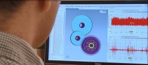
Simcenter 3D Motion Drivetrain can help reduce transmission simulation efforts by 80 percent and is a vertical application that enables engineers to easily define and simulate complex transmission systems based on industry standards. Hyundai engineers can simply enter basic parameters to define the configuration of a transmission system. From these parameters Simcenter 3D automatically creates the full 3D transmission model, including geometry. Hyundai engineers can then set gear contact parameters and operating conditions for the transmission, and the entire model is ready to solve in just minutes instead of hours or days.
Solving complex engineering issues

Additionally, transmission models can then be seamlessly integrated into Simcenter 3D Acoustics to perform gear whine analyses. According to Yang, “Simcenter 3D Motion Drivetrain is a useful tool that enables us to model the gear train with different levels of fidelity depending on our analysis requirements.”
“Thanks to our Simcenter Engineering and Consulting services project with Siemens Digital Industries Software, we hope to establish an efficient workflow to apply multibody simulation results to NVH and durability analysis and find the right software tools that fit our requirements,” says Yang.
It was important for Hyundai to find a solution that gave both the desired output and was easy to use. “From this perspective, the transmission builder software is well-suited for our engineering purposes,” says Yang. “It has a user-friendly interface.”
For more information:
Siemens Digital Industries Software
Phone: (800) 498-5351
www.sw.siemens.com


