In this approach, the local gear stiffness over the tooth depth is determined according to the Weber/Banaschek method (Ref. 3). The teeth are modeled as bending beams, with a cross-section that varies over the height. The deformation is influenced by the Hertzian contact, the shear deformation, and the clamping point of the tooth in the wheel body. The wheel body is considered as an elastic half-space. The majority of software packages use this method as the basic value for the gear stiffness, and it is also the foundation for the determining the gear stiffness according to DIN 3990 (Ref. 5) and ISO 6336 (Ref. 6). The additional change to the gear stiffness over the face width is considered using a plate model according to Schmidt (Ref. 7). This method is also implemented in the FVA-Workbench in the RIKOR (Ref. 8) and DZP (Ref. 9) calculation programs, and has been validated by both bench tests (Ref. 10) as well as decades of industrial application for the design of gear modifications. The advantage of this analytical formula-based method is that it produces reliable results for load distribution, noise excitation, and for the design of gear modifications with minimal calculation time.
The problem with previously available software-based implementations is that they only deliver precise results for the influence of cylindrical wheel bodies. The following solution will demonstrate how the analytical calculation of the influence factors can be extended to include detailed wheel body deformation calculated using FE methods, without significantly increasing the calculation time.
Determination of the Influence Factors Using an FE Approach
In this approach, the tooth deformation influence factors can be calculated using FEM. Here, both the gear and the wheel body are meshed. The mesh resolution is automatically determined according to a method developed in FVA Research Project 127 (Ref. 11), which is implemented in the FVA STIRAK calculation program and has also been validated in test bench trials and practical application. What is unique about this approach is that the parametric meshing is done using hexahedra for the tooth area to be evaluated and tetrahedra for the underlying wheel body. The two bodies are combined in the calculation process via mesh tying, also known as glued contact. This enables reliable FEM meshing of the gear, regardless of the complexity of the shape of the wheel body.
Similar to the Weber-Banaschek method, the influence factors are determined by applying a single load to discrete points and recording the deformation of the flank. For the FE calculation, these discrete points are the nodes of the FE mesh. The correct stiffness of the complete geometry, including the wheel body, is determined by superimposing the individual loads. The results show a slightly wavy surface for the pressure distribution. This can be smoothed by choosing a finer meshing resolution, but this increases the calculation effort.
The advantage of this FE-based approach is that the influence of the deformation of the wheel body is automatically considered. However, the calculation time is longer compared to the analytical approach.
Gear System Approach
To correctly determine the load distribution in cylindrical gear stages and design suitable gear modifications, all cross-influences between the machine elements of a complete gear system that are relevant for component deformation must be considered for the operating state to be calculated. The deformation behavior of the gearbox is represented in a complete stiffness matrix. The partial stiffness matrices of the individual components (casing, shafts, bearings, gears, couplings, etc.) are added to the complete stiffness matrix according to the method described in (Ref. 12). The deformation vector of the coupling points between the machine elements is determined by multiplying the inverted complete stiffness matrix by the load vector of the external loads.
To determine the partial stiffness matrices of each component, methods are used which deliver sufficiently precise determination of the deformations with a short calculation time. For example, the shafts are modeled in sections as classic Timoshenko beams. The bearing stiffnesses are determined according to (Ref. 13) based on the Hertzian contact deformation. FEM calculations are used for complex structural components such as the casing and planet carriers. A reduced stiffness matrix is determined for these components and then considered in the calculation. An example of this procedure is described in (Ref. 14). The system must be solved iteratively due to the non-linear behavior of the tooth contacts, the bearings in the gearbox, etc. This is done using the Newton method for iteration control.
How to Consider a Wheel Body
The gear stiffness from ISO 6336 (Ref. 5) is used throughout the mechanical system. This gear stiffness cγ describes the deformation behavior of two gears in mesh, and the model includes a fully cylindrical wheel body.
The gear stiffness is linked with the shaft via a rigid lever arm. The stiffness of the shaft can be modeled as either a Timoshenko beam or as an FE structure. This modeling method is shown in Figure 1.
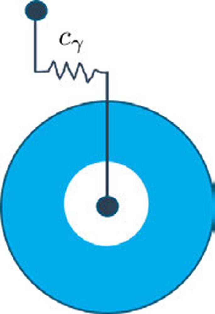 Figure 1—Analytical model using cγ from ISO 6336.
In an intermediate step, the gear stiffness is initially considered using a modified stiffness which does not include the influence of the wheel body. This is designated as cγmod, and the reduced stiffness of the wheel body is designated as kred. The gear pair stiffness is then linked at the level of the virtual bending diameter of the wheel body according to (Ref. 15). This type of modeling is shown in Figure 2. To link the wheel body with the shaft, rigid rods are added which transmit the deflections of the shaft and the torsion of the wheel body.
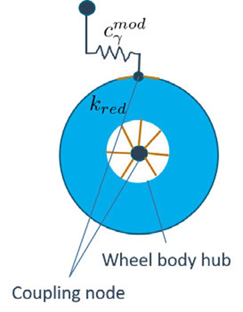 Figure 2—Integration of the reduced stiffness of the wheel body via a modified meshing stiffness.
In the following, a virtual node is introduced in the center of the hub and linked to the reduction point of the wheel body and the tooth pair stiffness. The connecting elements and the connection to the virtual node are rigid. This results in a system with identical mechanical behavior.
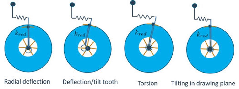 Figure 3—Possible deformation types of the model.
Considering the possible deformation cases shown in Figure 3, the advantages of this kind of modeling are clear. The common analytical models are limited to the bending of the tooth and the associated deformation of the cylindrical wheel body. In contrast, this model can represent all degrees of freedom. The radial deformation and its tilting in the drawing plane are important to consider for thin-walled structures, in particular.
To resolve the load distribution, reduction nodes are distributed at equidistant intervals across the common tooth width. The lever arms described above are applied at these reduction nodes. The shear influence in the wheel body is already fully considered via the static reduction.
The meshing of the surface is essential for the quality of the results. In particular, the distance between the nodes of the FE mesh and the reduction points has been observed to have an influence on the quality of the results. This imposes strict requirements on the quality and the resolution of the mesh. Special pre-processing of the CAD geometry of the wheel body makes it possible to fulfill these requirements.
Results and Discussion
The same model of a two-stage reducer gearbox, as typically used for electromobility, is used for all of the following analyses. The overall gear ratio of the gearbox is 1/7.76. The gearbox is driven with an input power of 100 kW at 5,000 min-1. The input torque at a nominal speed is specified as 190 Nm.
All of the following analyses focus on the input stage and describe its behavior. The gear data is summarized in Table 1:
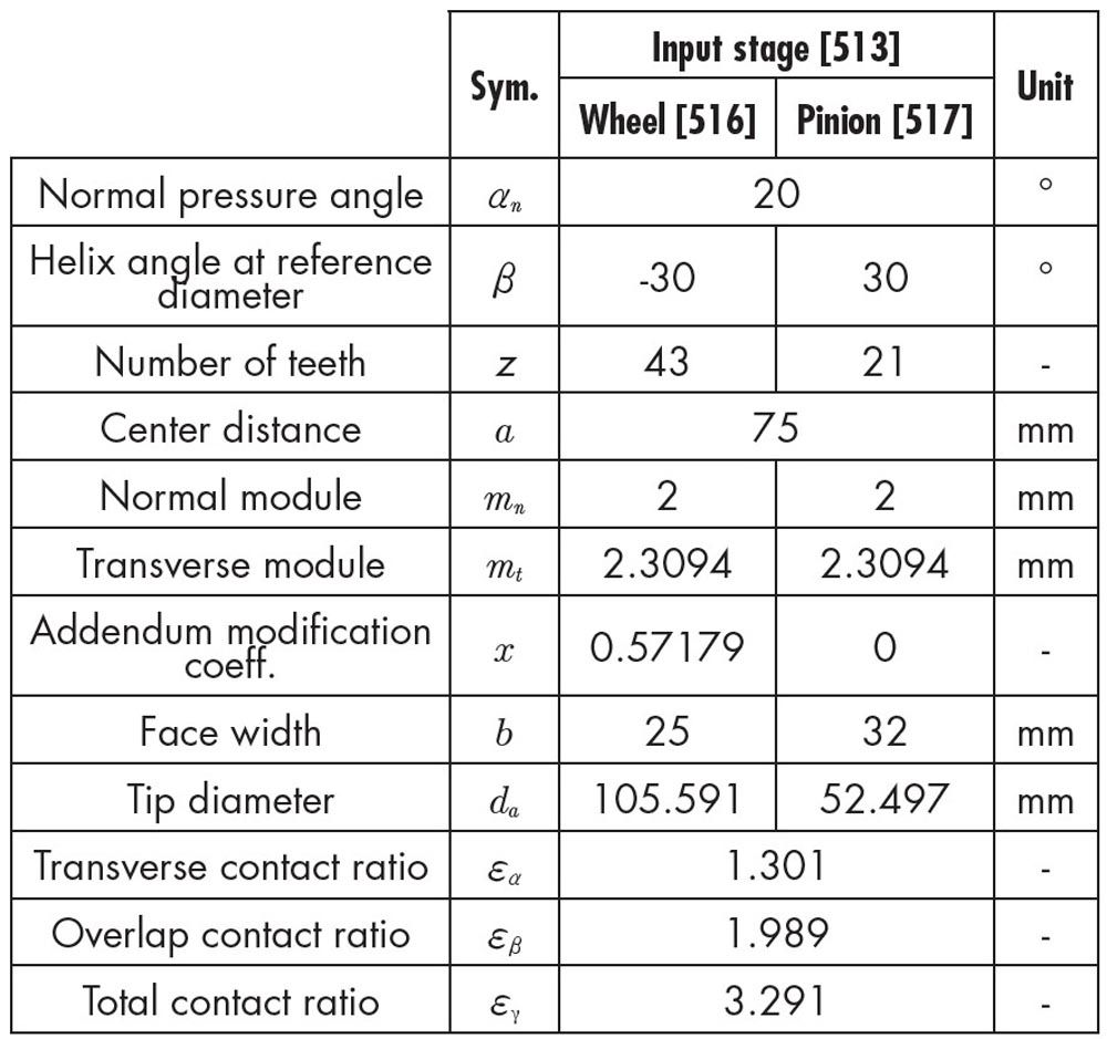 Table 1—Gear geometry.
The geometry of the wheel body is shown in Figure 5. The wheel body is fixed to the shaft via an interference fit. The geometry is largely determined by the outer diameter of the hub. The holes are positioned in the center between the outer diameters of the hub and wheel body to allow for holes with a maximum diameter.
The gear is modified to achieve uniform load distribution at nominal load. The full disc wheel body according to the Weber-Banaschek (Ref. 3) model is used as a reference. The 2D load distribution and the pressure distribution are shown in Figure 6.
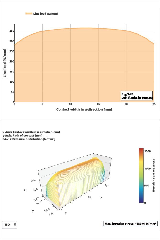
Figure 6—Loaded flank; load distribution over the tooth width (top), pressure distribution over the entire flank (bottom).
The applied gear modifications are specified in Table 2:
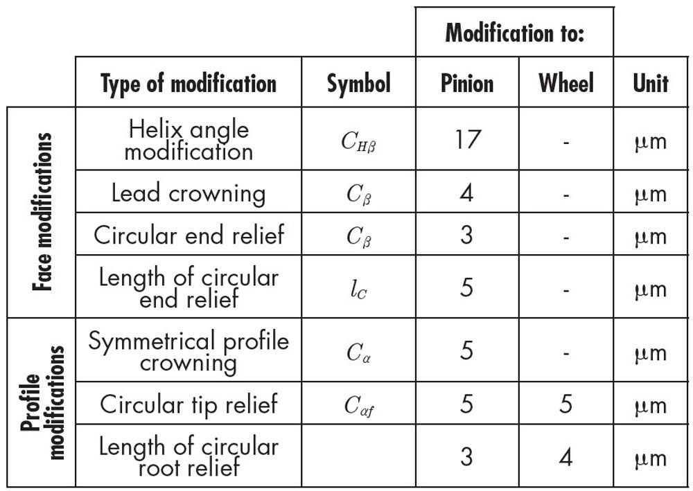 Table 2—Applied modifications.
This results in the flank and profile lines shown in Figure 7.
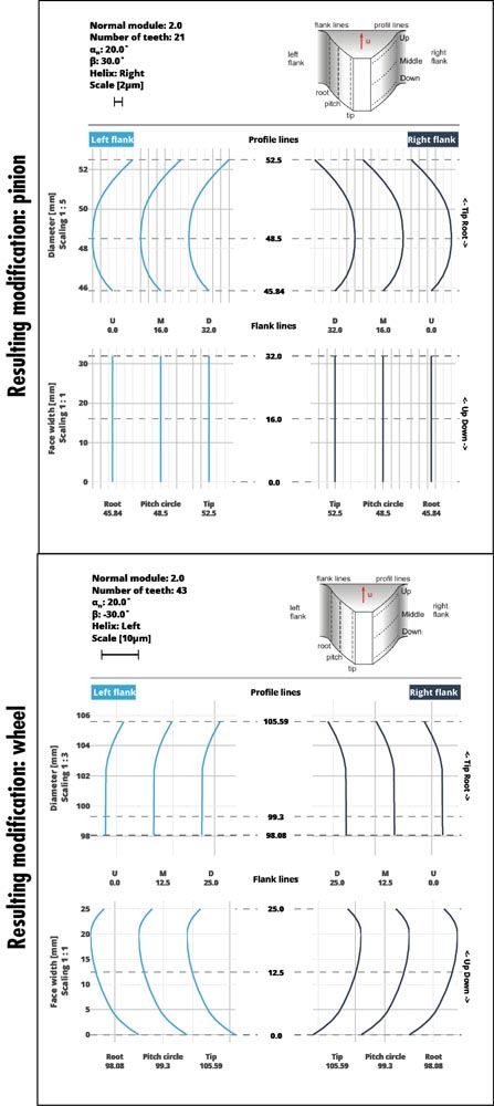 Figure 7—Resulting modifications for pinion and wheel.
Validation with Existing Models
First, the results of the cylindrical FE wheel body are compared with the results of the wheel body according to Weber-Banaschek. The width of the wheel body corresponds to the gear width. The diameter of the wheel body ends 3 * mn below the gear.
In a pre-processing step, the wheel body is meshed with tetrahedra and the stiffness is determined using static reduction. The mesh details are listed in Table 3.
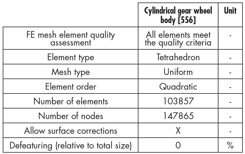 Table 3—Wheel body mesh details.The results of the calculation are shown in Figure 8. The graph on the left shows the result with the wheel body according to Weber-Banaschek, the reduced FE stiffness is on the right. The results are qualitatively very similar, and there is no difference in the transverse load factor KHβ.
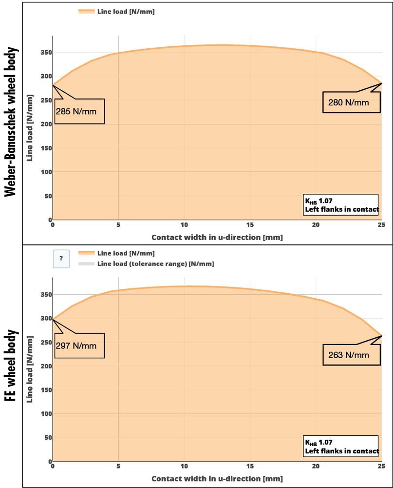
Figure 8—Comparison of the load distribution with (top) and without FE wheel body (bottom).
With the FE wheel body, a slight drop in the load (17 N/mm) can be observed at the right edge of the gear. At the left edge, the load increases by 12 N/mm. This indicates additional tilting in the tooth contact. Considering the deformations in the tooth contact, shown in Figure 9, it becomes clear that the additional tilting is caused by the lateral deformation of the wheel body.
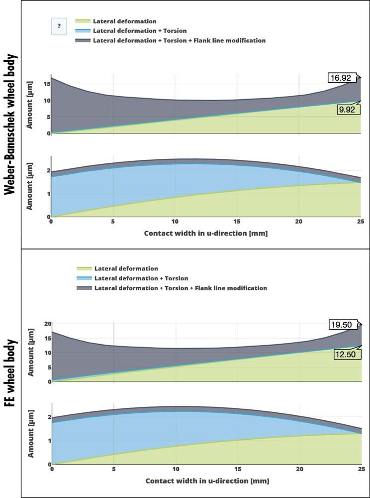
Figure 9—Deformation in tooth contact; with Weber-Banaschek (top) and FE wheel body (bottom).
Additional degrees of freedom are available with the FE wheel body, as shown in Figure 3. Due to the helical gears, an axial force acts on the gear mesh. In the axial direction, the wheel body behaves like a one-sided clamped cantilever. This deformation leads to additional tilting, in which the right side is pressed radially into the gear mesh and the left side is pulled out of the mesh. This increases the lateral deformation from 10 µm to 12.5 µm compared to the Weber-Banaschek model (Ref. 3).
The cylindrical wheel body is compared with an FE solution to validate the pressure distribution on the tooth flank over the gear mesh, using the FVA STIRAK program (Ref. 11) as a reference. For consistency, the meshing parameters defined in Ref. 16 are used for the FEM solution, as described in Table 4. To accelerate the calculation, only the teeth that come into contact are meshed. The total contact ratio determines the minimum number of teeth to be meshed.
 Table 4—FE meshing parameters for the gear and wheel body.
The calculated pressure distribution for the analytical solution with reduced FE wheel body and the FE calculation with STIRAK are shown in Figure 10. Direct comparison shows that the pressure distributions are very similar. The maximum pressure for the STIRAK solution is 1440 N/mm2, with 1381 N/mm2 for the analytical solution. This difference is considered negligible.
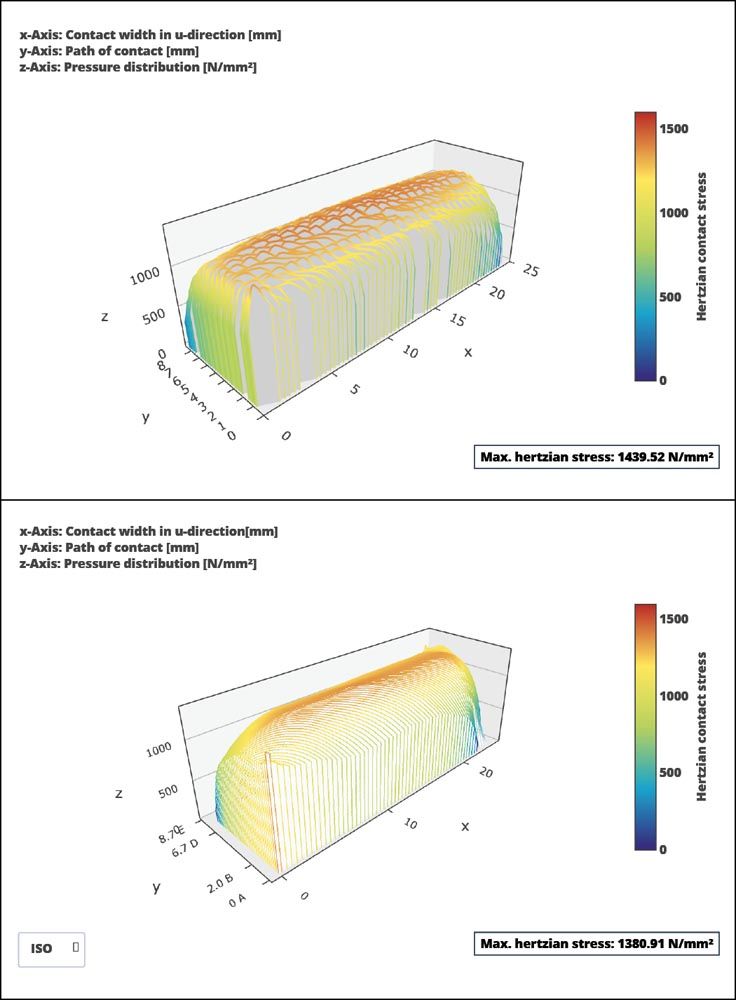 Figure 10—Pressure distribution comparison; pressure distribution with STIRAK (top), analytical pressure distribution with reduced FE wheel body (bottom).
Influence of the Wheel Body on the Gear Modification
The previous example clearly shows the influence that the axial force of a helical gear can have on the tilting of the wheel body. It can therefore be assumed that the web width will also have an effect on the gear modification. Thus, a wheel body will be calculated with a varying web width in this analysis. The geometry is documented in Table 5. As the load-carrying capacity of the wheel body cannot be considered with the available resources, it must be assumed to be sufficient. The wheel bodies are positioned such that the holes are always located directly under the gear for the calculation to maximize their effect.
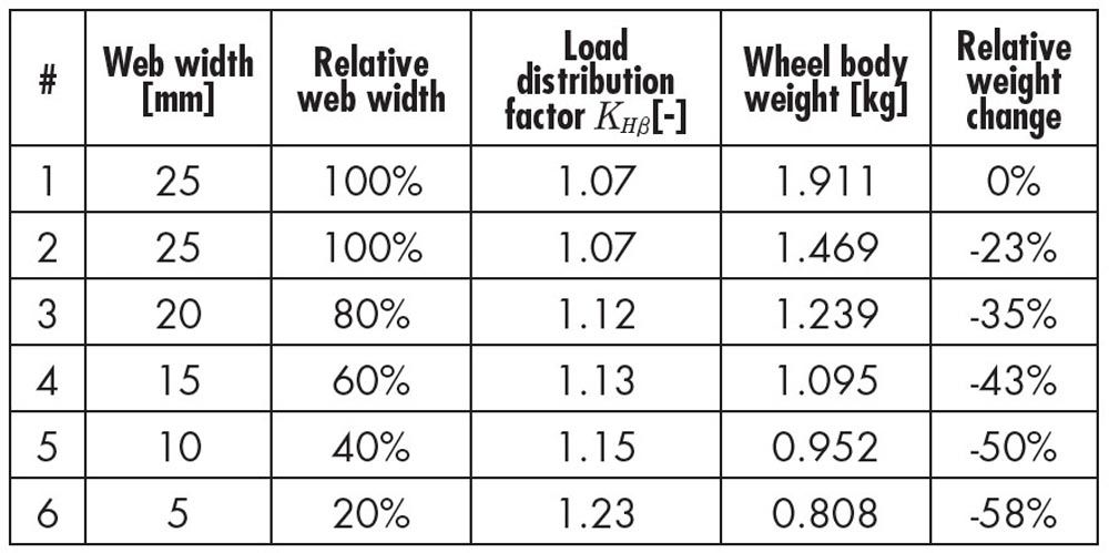 Table 5—FE meshing parameters for the gear and wheel body.
Variants 1 and 2 from Table 5 are cylindrical wheel bodies. Variant 1 corresponds to the calculation from the previous analysis; holes have been added to Variant 2 for additional weight savings. The holes are evenly distributed around the circumference and centered between the outer diameters of the wheel and hub.
Consideration of the relative weight differences between the variants clearly shows the potential of this type of wheel body. For example, a weight savings of over 60% can be achieved in Variant 6 with a web width of 5 mm.
Figure 11 shows the transverse load factor and the weight over the web width. As is to be expected, the graph shows that the weight decreases linearly with the web width. For the first two variants, it clearly shows that the holes do not have any effect on the transverse load factor. The transverse load factor increases as the web width is reduced. Surprisingly, moderate web widths only have a slight effect on the transverse load factor. In this case, the holes have no effect on the load distribution across the face width, as the wheel body was designed with a sufficiently thick gear rim. However, it can be assumed that the holes will have an influence on the transverse load factor with thinner gear rims.
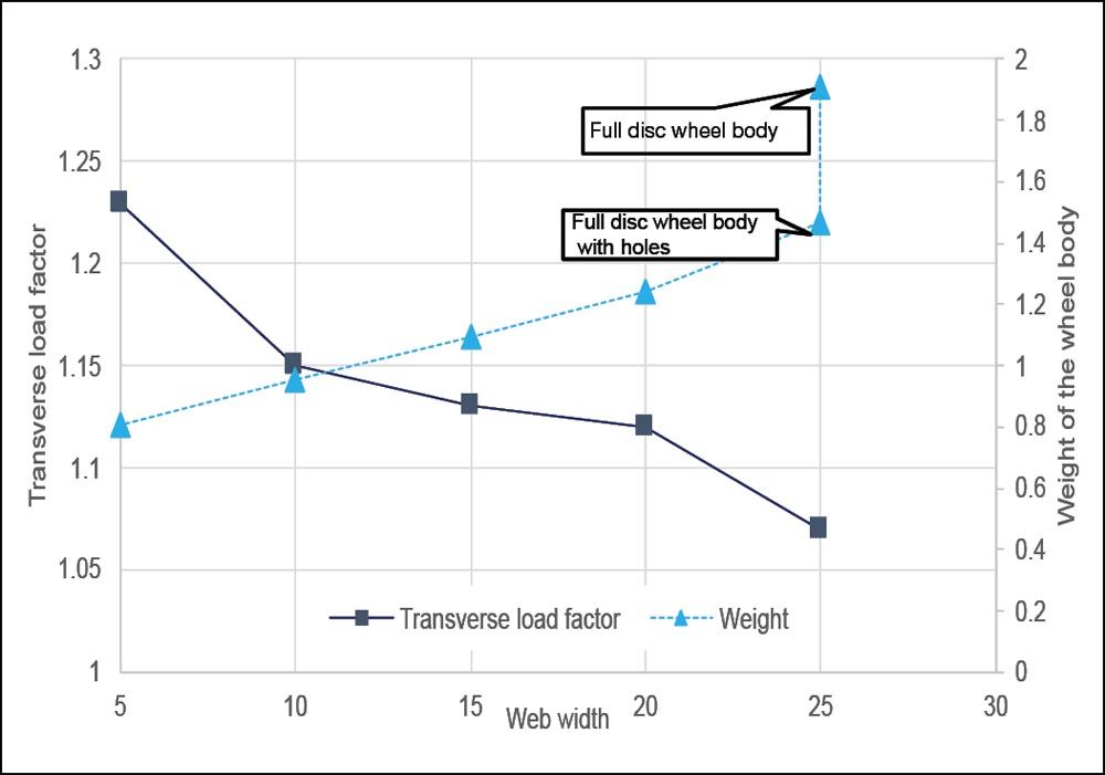 Figure 11—Transverse load factor and weight over the web thickness.
The additional deformation can be compensated for with a suitable helix angle modification. However, the modification to the drive and coast side flanks can differ significantly. It is essential that all relevant operating points are considered.
Influence of the Gear Body on the Noise Excitation
The previous results suggest that holes in the wheel body also have an influence on the tooth contact. Thus, the following will calculate four wheel bodies with different hole diameters. To more easily identify the influence of the holes in the evaluation, only four holes will be added. The analysis is performed using a wheel body with a web width of 15 mm to minimize its influence.
With this simulation technique, a rotating gear can be represented as rotation of the wheel body. The static reduction must be reperformed after each rotation. The rotational increment is one tooth.
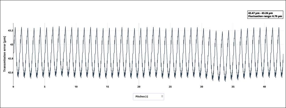 Figure 12—Transmission error of the gearbox input stage for a wheel body without holes.
To identify the influence of holes in the wheel body on the transmission error, a wheel body without holes is calculated in the first step. Figure 12 shows the transmission error over the angle of rotation of the wheel body. Qualitatively, it can be observed that the results fluctuate slightly. This is due to imperfections in the meshing. The transmission error curve shows a regular pattern with periodically recurring characteristics, as is to be expected from common excitation calculations. As long as no holes are included, the influence of the wheel body on the excitation is negligible. Harmonics can also be identified in the Fast Fourier Transformation (FFT) in Figure 13.
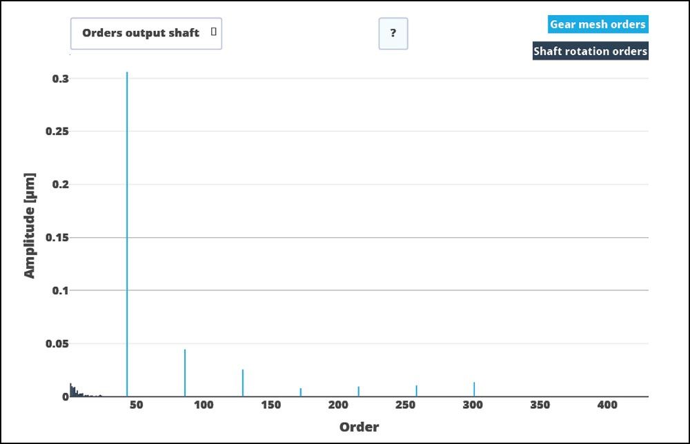 Figure 13—Transmission error spectrum of a wheel body without holes.
The meshing orders, marked as light blue lines, are particularly noticeable in the transmission error spectrum. The meshing orders are oriented to multiples of the number of teeth at the 43rd, 86th, 129th, and 172nd orders. Small amplitudes can also be seen between the first and 42nd orders due to harmonics in the transmission error and the meshing. These amplitudes occur when the reduction points are not located directly at a mesh node.
The following overview shows the excitation behavior for different hole diameters. The left column shows the transmission error, and the right column shows the spectra from an FFT.
Figure 14, which shows the transmission error over a single rollover and the associated FFT spectra, provides a summary of the calculation results. With regard to the transmission error, it can be seen that the magnitude of the oscillations increases with the hole diameter. The oscillation width increases more than nine-fold, from an initial 0.79 µm to 7.5 µm.
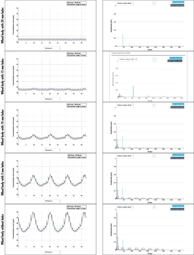 Figure 14—Overview of calculation results for hole diameters of 5 mm, 10 mm, 15 mm, and 20 mm.
Looking at the spectrum of the transmission error, it shows that the tooth meshing orders are predominant with small hole diameters. As the hole diameter increases, additional orders can be seen in the spectrum. From a 5 mm hole diameter, the 4th order is clearly visible as an additional order with an amplitude of 0.1 µm. This order increases with the hole diameter. With a 20 mm hole diameter, the 4th order greatly exceeds the defined axis with 2.9 µm. Furthermore, it can be observed that sidebands appear at the tooth meshing frequencies as the hole diameter increases, with a spacing of ±4 orders. These orders can all be attributed to the number of holes and the hole diameter. It can therefore be stated that the hole diameter and the number of holes have a clear influence on the excitation behavior. If the holes become too large, the excitation of the hole dominates over the excitations from the gearing.
In Figure 15, the ranges of variation of the transmission errors are evaluated. The fluctuation ranges are determined as maximum value—minimum value. The fluctuation range increases non-linearly with increasing hole diameter.
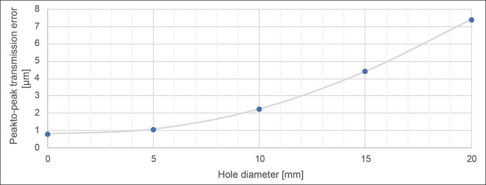 Figure 15—Influence of wheel body holes on the peak-to-peak transmission error.
It can be seen that the wheel body has a strong influence on the excitation behavior. This influence should be taken into account when designing the gear teeth and should be simulated using suitable tools.
Conclusion and Future Work
This study presents a simulation method for considering complex wheel bodies in an analytical tooth contact model. The wheel body is considered using reduced FE stiffness. Reduction points are defined over the width and linked with the analytical gear.
For cylindrical wheel bodies, comparative calculations show fewer deviations from the expected results with the new method. This is due to the additional degrees of freedom in the FEM model. In the calculation with cylindrical wheel bodies, bending due to axial force in tooth contact could also be verified in addition to the deformation in tooth contact and the influence of the shaft-bearing system.
The influence of the web width on the tooth contact could also be demonstrated in the analysis of the face modification. The axial stiffness decreases with the web width, and the wheel body deforms under the load. As long as they are known, these deformations can be taken into account via additional helix angle modifications. In doing so, it is important to consider partial load conditions, as the lower loads result in smaller deformations. This is also principally the case without the wheel body; however, the wheel body introduces additional elasticities into the system which must be considered.
It could be demonstrated that the noise excitation is particularly affected by holes in the wheel body. Holes can be detected in the noise excitation and in the spectrum, almost irrespective of their size. The larger the holes, the greater their influence on the noise excitation. In particular, the low-frequency vibration components, such as the amplitudes from the hole, become significantly more important with increasing speeds in electrified powertrains. While lower speeds were common in the transmissions of internal combustion engines, higher speeds are frequently used in electric drives. For example, the speed4e concept drive (Ref. 17) uses 30,000 rpm on the drive side.
The heavy dependence on the finite element (FE) meshing quality poses a challenge, as the user must deal with different meshes and perform a convergence analysis to find the appropriate meshing quality. It would be preferable to specify a structured mesh on the surface at the transition between the FE wheel body and the analytical gear. This would ensure that the reduction points are always located on the nodes of the FE mesh.
Fast simulation is essential for being able to calculate the influence of the wheel body on the gear as early as possible in product development. With this simulation method the greatest effort is the static reduction, which must only be performed once. The calculation times were documented in the project and are summarized in Table 6. These speeds suggest that this method is suitable for product development.
 Table 6—Summary of calculation times.
In conclusion, it can be stated that the use of weight-optimized wheel bodies is possible and useful. However, this should be considered in gear calculations as early as possible, as the wheel body has an influence on both the load-bearing capacity and the noise behavior.
References
- Wimmer, J. A., 2006, “Cylindrical Gear Load Losses: Design Influences, Efficiency Maximization, Tribology,” Ph.D. thesis, TU Munich Gear Research Center (FZG).
- FVA Research Project 484 V, Elastic Wheel Bodies, Forschungsvereinigung Antriebstechnik e.V. (FVA).
- Weber, C. and Banaschek, K., Form Modification and Profile Relief of Cylindrical and Helical Gears. Antriebstechnik series of publications 11, Vieweg Verlag, Braunschweig.
- FVA-Workbench Version 7.0 – Description of Modules (2022), FVA GmbH.
- DIN 3990-1:1987-12: Calculation of load capacity of cylindrical gears; introduction and general influence factors, Beuth Verlag (1987).
- ISO 6336-1:2019-11: Calculation of load capacity of spur and helical gears—Part 1: Basic principles, introduction and general influence factors, Beuth Verlag (2019).
- Schmidt, G., 1972, “Calculation of the Rolling Contact Pressure of Helical Gears and Consideration of the Pressure Distribution,” Ph.D. thesis, TU Munich Gear Research Center (FZG).
- FVA Research Project 30 I–VII: Pinion Modification Program—RIKOR, Forschungsvereinigung Antriebstechnik e.V.
- FVA Research Project 338 I–VII, Dynamic Tooth Force Program—DZP, Forschungsvereinigung Antriebstechnik e.V. (FVA).
- FVA Research Project 592 I–II: Validation and Investigation of Application Limits of the FVA RIKOR Gear Program Based on Deformation Measurements, Forschungsvereinigung Antriebstechnik e.V. (FVA).
- FVA Research Project 127 I–IX, STIRAK FEM Tooth Contact Analysis, Forschungsvereinigung Antriebstechnik e.V. (FVA).
- FVA Research Project 571 I, Planetary Stage Load Distribution in the FVA-Workbench, Forschungsvereinigung Antriebstechnik e.V. (FVA).
- Breuer, M., Theoretical and Experimental Determination of Rolling Bearing Stiffness, VD Progress Reports, Series 1, No. 241 (1994).
- FVA Research Project 711, Integration of Elastic Casing Structures in Gearbox Design with RIKOR and Visualization of the Entire Transmission System in the FVA-Workbench, Forschungsvereinigung Antriebstechnik e.V. (FVA).
- Wikidal, F., 1998, “Calculation of the Flank Pressure of Cylindrical and Helical Gears Under Consideration of Load and Production-Related Deviations,” Ph.D. thesis, TU Munich Gear Research Center (FZG).
- FVA Research Project 892, FE Calculation of Plastic Gears in the FVA-Workbench, Forschungsvereinigung Antriebstechnik e.V. (FVA).
- Speed4E project website: speed4e.de/Joomla/index.php/e


