Happy New Year! I hope everyone had a little time off over the holidays. We’re just getting into Michigan’s bi-polar winter season where leather coats are being hung up in favor of sub-zero parkas.
I had a couple of recent conversations with different people regarding ball bearing fit practices. We have covered this before, but these issues reminded me that the topics of fit and clearance are always fair game. If you enjoy ambiguity and uncertainty, there are few better places to start than fitting a small ball bearing with tight clearance. Just to keep things simple, I’ll use Koyo’s (JTEKT) main Ball & Roller Bearings catalog for the technical information. All full-size bearing catalogs will have the same information.
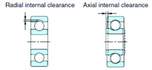
The place to start when determining fit is with clearance. When dealing with ball bearings, the term “clearance” always means radial internal clearance, whereas when we preload tapered bearings, we are usually talking about axial preload/endplay (Fig. 1). For your reference, axial clearance is around 10x the distance of radial clearance.
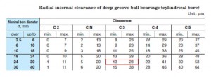
Let’s just walk through a quick example with my favorite bearing, i.e. — 6205. When ordering these you must know what clearance you are ordering; this will usually be indicated somewhere in the title. Even though there is a “normal” clearance designated with CN, C3 is by far the most common clearance.
Ok great — you now have a C3 6205; what does that mean? Fortunately, ISO ball bearings are very standardized, so you can find clearance tables similar to Table 1 just about anywhere online or in any catalog, and it will be the same for any brand. Since a 6205 has a 25 mm bore (multiply the last digit by 5), under the C3 column you see that we have a clearance range of 13 – 28 microns (µm). This is basically how much room we have to work with. Unlike tapers, we do not want to preload a ball bearing. There are a few situations with lightly loaded bearings where you can add a light axial preload via spring or similar method; but we will never try and radially preload a ball bearing.
For most normal ball bearing applications, you will want an interference fit on one ring and leave the other ring loose or leave the other ring as a loose fit (aka clearance fit). There are three reasons for this: 1) there is not enough internal clearance in the bearing to press both rings; 2) one slip ring prevents over-constraining the bearing system; and 3) without special tooling you will need to press one of the rings through the bearing, which is a huge mistake (e.g., pressing the bearing into the housing with the shaft). You will damage the bearing by doing this. If you need to constrain the loose ring, you need a mechanical retainer such as a snap ring.
When possible, the rotating ring should have the interference fit. The only reason for this is that the turning ring is mostly likely to try to walk around the shaft due to inertial effects. Some light walking or creeping is harmless as long as you aren’t moving material or creating heat. For our 6205 example, let’s say we are pressing onto a rotating shaft, which carries a stationary load.
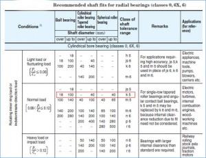
Table 2 gives us a recommendation, but we still need to do more work. If we are working with a normal load (6-12 percent of the dynamic load rating), a k5 shaft fit is recommended. Usually hidden somewhere in the appendices there will be standard shaft and housing fit tables. As shown in Table 3, our 25 mm shaft diameter has a k5 fit of +2 / + 11 µm. These dimensions are applied to the diameter class of the bearing (not the average diameter). For instance, a 6205 has an inner ring diameter tolerance of -10 µm, leaving the true average around 24.995 mm, rather than 25.0. Fit tolerances are applied to 25.0 mm. For our 6205 the recommended shaft is 25 +2/+11. Sometimes unilateral tolerances can make for easy proofing (rather than 25.002/25.011); your choice.
You may quickly realize that you have been handed a 9-micrometer tolerance to work with. This is tighter than the bearing tolerance that you are buying and, for most places, unrealistic. A k7 or k8 is the more likely reality for most places. You can see that all of the fits in the k series have a minimum press of 2 µm. I will often use 5 µm as a minimum threshold for a “press fit,” but I’m not going to argue about 3 µm. Where the hand-wringing starts is when we look at the stack-up for these fits. Again recalling that our inner ring has a -10 µm tolerance, a k5 leaves with a fit range up to 21-µm interference. All things considered, the residual clearance ranges from 11 µm interference to 26 µm clearance.
But what about the clearance?
Ok, there is a slight caveat; you can have a little radial preload before you fall off the edge. The reason I recommend not trying to design this in is, as you can see, trying to avoid any chance of preload would leave you with a very loose shaft on the other end; that will create problems for you. As we are threading this needle, the small amount of potential preload at the limits can be tolerated (more so than an excessively loose shaft).
Now let’s see how this looks with a more realistic range. For me, I would target about +5/+30 for this application. That puts our effective clearance at 16 µm interference to 24 µm clearance. If you are looking for a rule of thumb for how far you can play this game, I like to have my clearance range about 2x the interference range. Statistically, this will rarely get you into the fringes of your clearance window. My +5/+30 would be a few microns on the tight side, but with a bearing that has a healthy life margin, there is nothing to worry about. If I were pushing the life limits of the bearing, I might back down to +2/+27. Many bearing suppliers will agree with this approach; some get nervous when relying on statistics. This is just the reality of bearing fits.
The housing fits are quite a bit easier. Start with a line to line fit and let your tolerance decide the upper end. So for my 6205 with a 52 mm outer diameter I am going to set my lower housing diameter at 52 and the upper end is going to be whatever I can hold. Easy breezy.
Follow these simple rules and your fits will be perfect:
- Know your bearing clearance, dimensions and tolerances up front.
- Press fit one ring (preferably the turning ring) and slip fit the other. Follow the tables for guides, but also double-check your stacks to make sure you aren’t running more than ~ 30% into potential preload.
- Start line to line on the housing. Too loose of a housing can create alignment and/or noise problems. Sometimes too close of a housing fit can be difficult to install. Adding a little oil to the outer ring is common practice. Leave opening up the diameter as a last resort.