Figure 1—Torque over time in the time series (left). Torque on a specific tooth of the pinion (right).
If the signs of torque and speed in a time series are in such a way that always the same flank is in contact, then the so-called simple-count method can be used. The counting method is also documented in ISO 6336-6, Table 4 (Ref. 3). To obtain the load spectra for fatigue damage calculation, the range of the measured (or calculated) load is divided into bins or classes. If the speed is significantly varying, then for better results speed intervals are also created and each measuring point is sorted into the corresponding category of torque and speed. The number of measuring points is then counted and results in a load spectrum of bins with different torques and speeds (extended simple-counting method), see Figure 2.
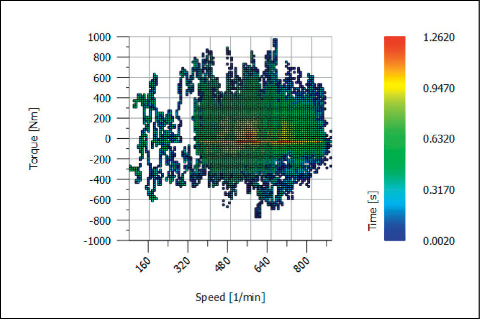
Figure 2—Display of the result of the extended simple-count method, torque-speed distribution with indication of duration in seconds.
If torque and/or speed have alternating signs so that the loaded flank is changing, then the assessment of the Hertzian pressure on the considered tooth flank (left or right) only considers the positive values on this flank. For the bending stress, this simple calculation procedure cannot be applied. The considered tooth root side is subjected to an alternating load, receiving tensile stress with positive torque and compression stress with negative torque. All significant alternating load cases must be extracted from the torque curve through the rainflow-counting algorithm. The result of the algorithm is a half-matrix displaying the count of how often a torque change Thigh-Tlow happens (Figure 3).
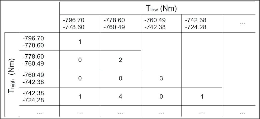
Figure 3—Extract of a Rainflow half-matrix with 100 bins.
ISO 6336 is designed for the pulsating load on the tooth, meaning the nominal torque and the allowable bending stress numbers are intended for the pulsating load case. In general mechanics, a load case is defined by the stress ratio R (Ref. 5). It is the ratio between the lowest and the highest stress occurring as the stress oscillates during operation. So, for the pulsating load case, the ratio is R = 0 (as the stress is oscillating between 0 and σhigh).
General definition of the stress ratio R (Ref. 5):

(1)
As the bending of a tooth the stress σb is proportional to the nominal tangential load Ft; and as Ft is proportional to the torque T, for tooth bending the ratio R can also be expressed as follows:

(1a)
For alternate bending, in ISO 6336-3, annex B (Ref. 2), a rule is given to cover load cases with stress ratios 1 ≤ R ≤ 0 with the alternating bending factor YM (see Eq. 1). As the general case of R may be in the range from -∞ R ≤ + 1, the formula for YM must be extended as documented in Ref. 1. Then a set of {Thigh, Tlow} can be converted in {Thigh, YM1 and YM2} per ISO 6336 nomenclature.
Note that in ISO 6336-3, annex B (Ref. 2), the definition of the stress ratio R appears to be different from Equation 1, but in fact is not. In ISO, the load Ftlow is the load applied on the opposed flank (positive value) but creates compressive bending stress (negative) on the considered flank. Furthermore, the compressive stress should be multiplied by 1.2 since the compressive stress on the nonloaded flank is approximately 20% higher than the tensile stress on the loaded flank. The factor 1.2 is used in ISO 6336-3 and can be confirmed with FEM calculations. So, the stress ratio definition according to Equation B.2 in ISO 6336-3 with R = -1.2 *Ftlow / Fthigh is identical to the definition as used in general mechanics (as above).
Every element of the rainflow half-matrix must be converted in a bin of the duty cycle. To be in accordance with ISO 6336-6, a bin will contain the operating hours per bin, torque, speed and additionally the alternating bending factors YM1, YM2 for the gear pair. The full procedure (Ref. 1) to convert time-torque-speed data into a duty cycle for gears is complex, see Figure 4.
When torque and/or speed have alternating signs, the rainflow method must be used to catch all significant changes from positive to negative load. The rainflow method will find many load changes occurring during the measured time frame, independent of the speed information. So, the speed information cannot be considered and is lost. Therefore, the mean speed is used in the resulting load spectrum.
Generation of a Load Spectrum for Bearings
Bearing forces depend on the loads applied on the related shaft. The signs of torque and speed applied on the shaft are not relevant for bearing verifications. But speed variation must be considered, so the extended simple-counting method (see Table 2), generating a load spectrum with load and speed distribution, is the appropriate method.
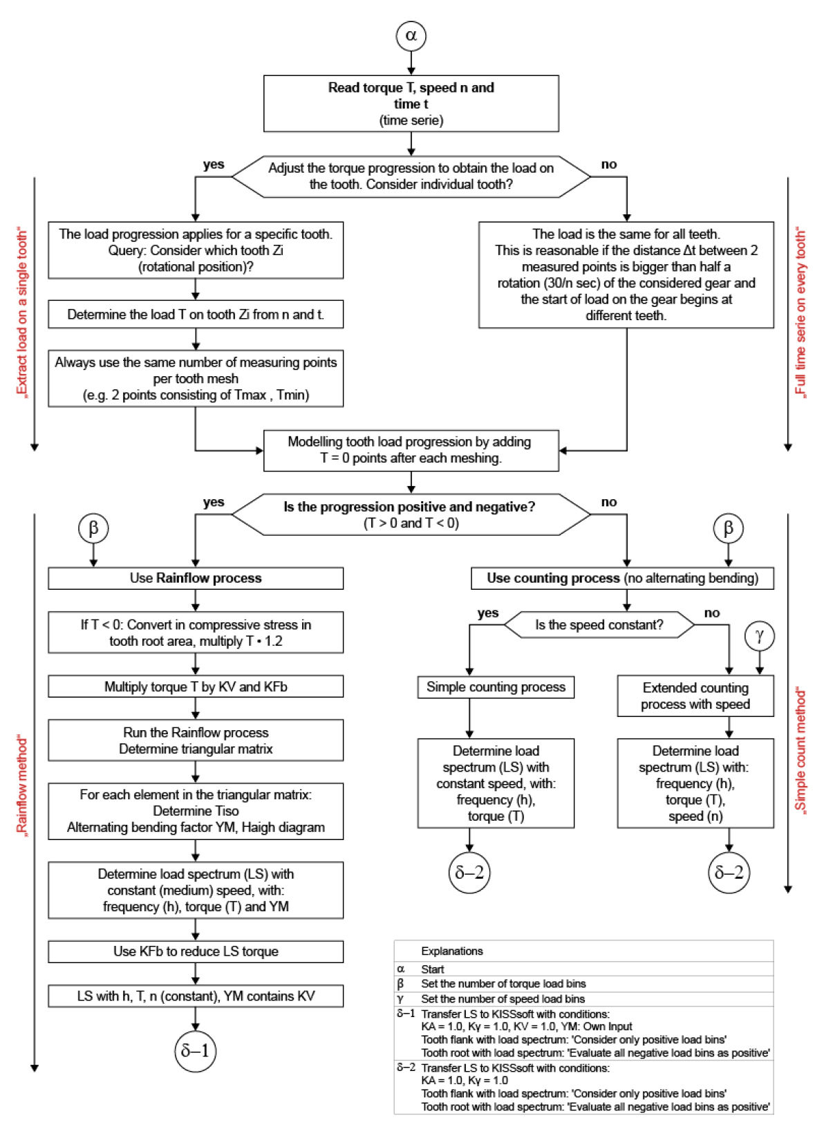
Figure 4—Flowchart to generate a load spectrum for gears from time series data.
Generation of a Load Spectrum for Shafts
Shafts in drive systems are submitted to bending, axial tension/compression, torsion, and shear stresses. A point on the outer diameter of a rotating shaft is submitted to tensile stress in one position and to compression stress when rotated by 180° (Figure 5). Therefore, a rotating shaft with gears submitted to a varying torque - when the torque changes slowly (much slower than the shaft speed)—is basically submitted to alternating bending and shear stress. In contrast, torsional stress is nearly constant, changing much slower according to the changes of the applied torque. In simplified calculations, torsion is often assumed to be pulsating (assuming that the torque is pulsating with every rotation). This assumption is on the safe side, as normally the change in torsion per rotation is much less.
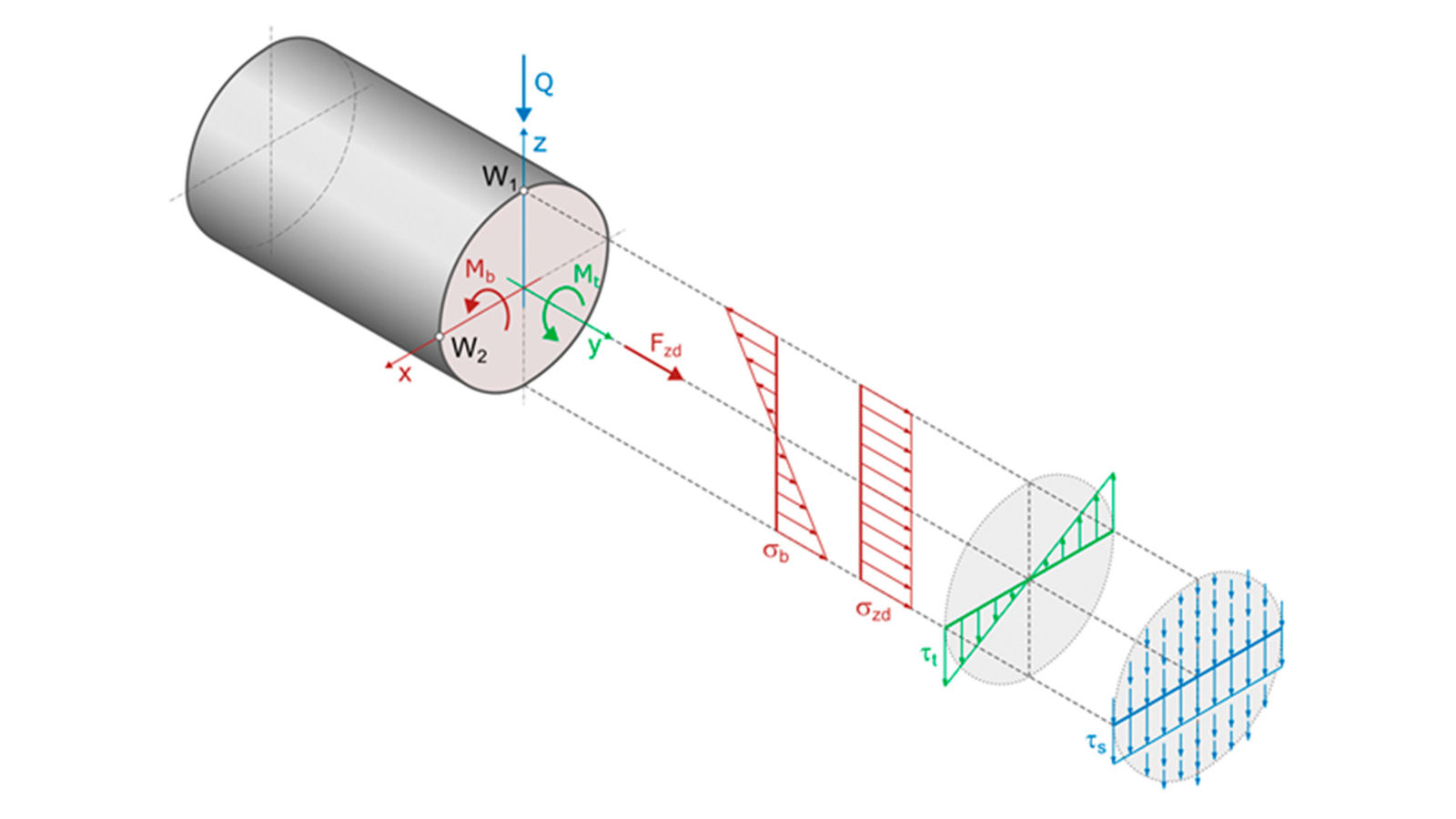
Figure 5—Stress distribution for tension/compression, bending, torsional, and shear stress in a shaft.
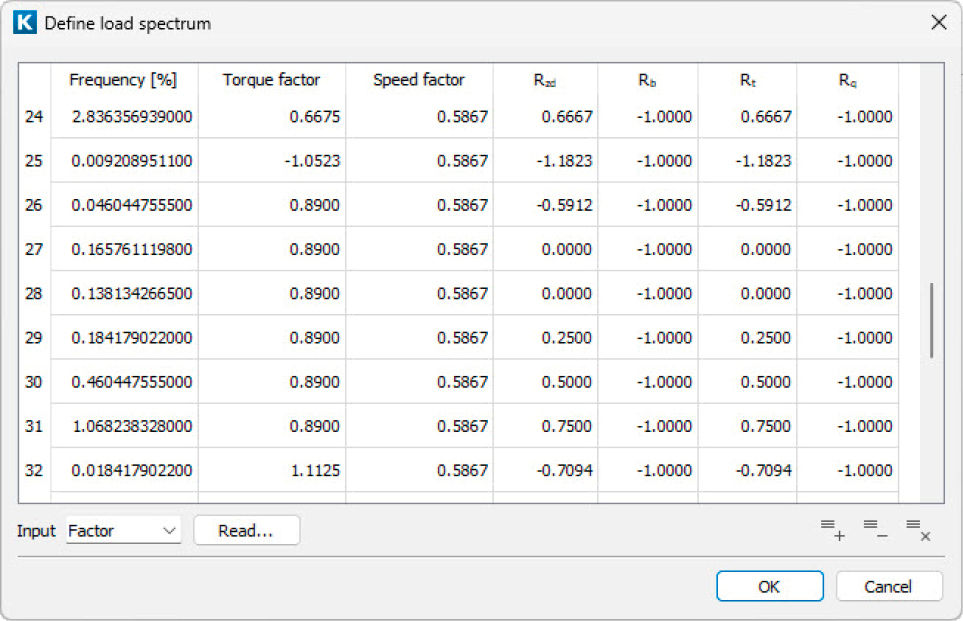
Figure 6—Load spectrum for shaft verification (extract displaying bin 24 to 32), torque and speed as factors to be multiplied with the nominal values).
If the real number of torque changes is extracted from time-torque data by the rainflow method, then the torsion stress distribution is more realistic and will provide improved results. The same considerations apply also to axial tension/compression stresses.
The rainflow analysis delivers the upper torque Thigh and the lower torque Tlow of a load spectrum bin. For a shaft calculation according to the FKM rule (Ref. 5) the upper torque Thigh and the stress ratio factor R is used (see Equation 1). Thus, a load spectrum bin must additionally contain the R factors for torsion and axial tension/compression according to Equation 1, and R = -1 for bending and shearing. For further handling of Thigh and R see the section “Rating of Bearings with a Load Spectrum.”
Note that in the shaft section, where bending and torsion stresses are combined, often the bending stress dominates, making the influence of torsion minimal. In such cases, assuming that torsion is pulsating is acceptable. The advantage of this simplification is that shaft and bearing calculations can use the same load spectrum (Type A according to Table 2).
Rating of Machine Elements with a Load Spectrum
The rating of machine elements of a drive system is defined by national or international standards. Generally, a standard provides the calculation methods for the rating with a nominal load. Rules for the consideration of load spectrums are often missing. In this chapter, the methods for the verification of the most critical elements—gears, shaft, and bearings—with a load spectrum are discussed.
Rating of Gears with a Load Spectrum
Part 6 of the ISO6336 standard is the rule for the “Calculation of service life under variable load” (Ref. 3). The method is based on the Palmgren-Miner rule, which is a widely used linear damage accumulation method. The method is “neutral,” which means specific factors of the rating method used are not involved. Therefore, this rule can also be used in combination with AGMA ratings (as AGMA 2001 (Ref. 4) and others). AGMA rating methods do not give a rule for nonuniform load, but reference is given to use Miner’s rule as presented in ISO/TR 10495 [Chapter 7.2 in Ref. 4]). ISO/TR 10495 was replaced in 2006 by ISO 6336-6.
To also handle cases with bins having negative torque (tooth loaded in the compressive stress domain) the rule for the alternating bending factor YM has to be extended (Ref. 1); and for every bin an individual YM1 and YM2 must be used.
Rating of Bearings with a Load Spectrum
A rule for the rating of bearings with load spectrum is not available in an international standard. The calculation procedure is based on the damage accumulation theory developed by A. Palmgren in 1924 and completed by B.F. Langer (1937) and M. Miner (1945). The formulae are well documented in the literature (Niemann-Winter [Ref. 9]) or in handbooks of bearing manufacturers (Ref. 10).
The main formula for the calculation of the total bearing service life by combining the service life per bin is documented in Equation 2. Service life may include the effect of lubrication and/or the modified reference rating according to ISO 16281 (Ref. 11).

(2)
Rating of Shafts with a Load Spectrum
The rating of shafts is not widespread. Until today, no ISO standard is available. Some national standards exist, but they are limited. DIN 743 (Ref. 8) contains indications concerning equivalently damaging stresses. But the only official method, that can cover and complete this task, is the German FKM Guideline (Ref. 5).
It must be noted that the symbols used in the FKM guideline are based on former East German TGL standards and unfortunately quite different from symbols used otherwise in literature, DIN, or ISO standards. All symbols used are listed in the symbol table of this paper.
The FKM Guideline contains variants of the calculation procedure for steel or other materials, as well as welded and nonwelded machine parts, and is therefore quite complex. For shaft verifications, the fatigue strength assessment with nominal stresses must be carried out. In this paper, only the main steps of the calculation with nominal stresses for steel using the method “Miner elementary” with the “equivalent amplitude assessment” rule (Ref. 5) will be summarized.
For shaft verification normally different shaft sections are selected, where a detailed analysis is made. In a section of a shaft, in general, there are different acting stress types: axial stress (tension or compression) Szd, bending stress Sb, torsional stress Tt, and shear stress Ts. Their maximum and minimum values (Smax, Smin or Tmax, Tmin) must be used. With a load spectrum, for every bin of the spectrum, in a determined section of the shaft the maximum loads must be calculated (axial force Fzd,max, bending moment Mb,max, torsional moment Mt,max, and shear force Q,max). Then the corresponding maximum stresses (axial Szd,max, bending Sb,max, torsion Tt,max, shear Ts,max) are found, using well-known equations (as in AGMA 6001, chapter 4.4, Ref. 13 or in Ref. 5, formula 1.1.1). The minimum stresses can be derived with the ratio factors:
Stress amplitude Sa, mean stress Sm, stress ratio R:

(3)
The stress distribution in a shaft section is complex and different for the four acting stress types (Figure 5). At a specified point of a shaft section, the resulting stress is a combination of the four stress types, according to the normal stress hypothesis or the von-Mises criterion (Ref. 5). For nonwelded steel von-Mises is preferred. Usually, two points at the position W1 and W2 (Figure 5) of a shaft section are the highest loaded and should be checked.
Verification with nominal stresses consists of a static strength assessment and a fatigue strength assessment. The static strength is checked with the bin of the load spectrum with the highest stresses. So for every bin the resulting combined stress (using the maximum stresses Szd,max, Sb,max, Tt,max, Ts,max) is calculated, and the verification is made with the highest value found. According to FKM the static assessment against the tensile stress Rm and against the yield strength Rp must be performed. Additionally in case of higher temperatures, the assessment against the creep strength Rm,Tt and against the creep limit Rp,Tt is required.
Fatigue Strength Verification
For the fatigue strength, the stress amplitudes (Equation 3) of all bins are relevant, contributing to the damage accumulation. The equivalent amplitude Sequ used in FKM is a constant stress amplitude with an assigned cycle number equal to the knee point of the S-N curve, which is damage-equivalent to the related stress spectrum under consideration of the shape of the S-N curve, the required total number of cycles and the maximum amplitude in the spectrum. The description of the verification proceeding with all formulas would exceed the purpose of this paper. So only some of the important steps will be presented.
For every stress component (axial, bending, torsional, and shear) the same procedure is applied. In the first step, the mean stress value with amplitude (stress Sm.i and Sa,i) of every bin is converted in an equivalent alternating stress with amplitude SaW.i (with Sm.i = 0 and SaW.i). Then the range of bins must be resorted, such that the first bin has the biggest amplitude (SaW.1). In the third step, the variable amplitude factor must be found, using Equation 4 and Equation 5.
The variable amplitude factor KBK, Equation 2.4.39 in FKM (Ref. 5), is

(4)
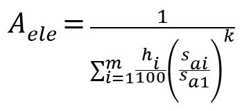
with Aele, the distance between fatigue life curve and SN-curve, Eq. 2.4.42 in FKM [5],
(5)
with k, the exponent of the SN-curve (for steel k = 5 for normal stresses and k = 8 for shear stresses).
This permits obtaining the equivalent stress amplitude at the knee point of the SN-curve, Sequ, FKM Equation 2.4.27 (Ref. 5).

(6)
For the fatigue strength assessment, depending on the position of the considered shaft section, at locations with shaft shoulders, keyways, etc., the stresses are increased due to local stress concentration. In the FKM (Ref. 5), as in AGMA 6001 (Ref. 13) or DIN 743 (Ref. 8), for the verification the nominal stresses are used (not increased), but the fatigue strength is modified (reduced) by stress concentration factors. As mentioned in AGMA, “since the fatigue strength is largely influenced by physical conditions, environmental conditions, and application conditions as well as material conditions, the basic fatigue strength must be modified (Ref. 13)”. In FKM (Ref. 5) all these effects are documented and combined in the so-called “design factor” KWK. So, the component fatigue limit for axial, bending, torsional and shear are reduced by the design factor per component to obtain the effective nominal values of the component fatigue limit SWK, TWK.
In ISO or AGMA ratings, the final result of a verification is the safety factor obtained by division of the permissible stress by the effective stress. The resulting safety S must then be equal to or higher than the minimum requested safety Smin. The result obtained by FKM is not a safety factor, but the “degree of utilization.” The degree of utilization is just the inverted value of the safety factor. The advantage of the utilization concept is that formulas for the verification with combined stresses are simpler. For this paper, the safety concept is used, and the FKM formulas are adapted accordingly. As a symbol for safety, we use here SY, as the symbol S in the FKM guideline is used for nominal stress.
The basic equation for component safety SY, equal to the inverted value of the degree of utilization aBK according to FKM Equation 2.6.3 (Ref. 5), for axial, bending, torsional, and shear are:

(7)
So, based on the applied stress and the permissible stress per component, the safety factors obtained are SYBK,zd, SYBK,b, SYBK,t, and SYBK,s. For the consideration of the combined stresses in a shaft, these factors are then combined according to the von-Mises criterion (Equation 2.6.7, FKM [Ref. 5]) to obtain the final result.

(8)
In a shaft section, there are two locations where the combined stress may be highest, position W1 and W2 in Figure 5. In point W1, bending and torsion stresses are high, but shear is zero. In W2, shear and torsion stresses are high, but bending is zero. Thus, both positions must be checked to find the lowest safety factor.
The verification of whether the shaft section fulfills the request is then given by:

(9)
with the requested minimum safety factor jD for fatigue strength assessment. For cases where the consequences of shaft failure are high, this factor can be assumed to be 1.5.
Verification of Drive Systems
Today the analysis of drive trains is performed with appropriate software such as KISSdesign (Ref. 12) which permits modeling the complete drive with all the main elements. Normally the time series is measured at the input or the output coupling. The handling of a time series for a drive train can be made in two different ways.
- The “simple variant,” using the same load spectrum for each element of the drive
- The “general variant,” generating individual load spectrums for different elements (such as gears, shafts, bearings) and for each stage of the drive
Use of Time Series for Drive Systems with the Simple Variant
A load spectrum of type A (Table 2) must be defined at the input or output of the system, at the location where the time series was measured. This load spectrum is then used across the drive system for all gears, shafts, and bearings. For this scope, it is preferred that torque and speed in the load spectrum are given as factors to be multiplied by the nominal values (see Figure 6). The drive train software will calculate the nominal speed/torque of every single element, and the same load spectrum, if defined with factors, can be used everywhere.
The simple variant can be used with any drive system software permitting the use of load spectrums without any further adjustment. If the torque and speed of the time series are always positive, or if some infrequent negative values can be neglected, then this method is preferred. The results for gears and bearings will be perfect, load spectrum of type A is used. For an accurate shaft verification, always load spectrum of type B should be used, otherwise, the shaft strength will not be accurate. Often shaft strength is not critical. The use of load spectrum type A—and assuming the torsion and shear as pulsating for shaft verification—will produce conservative results (on the safe side). So, if the results are satisfying, there is no need for a more complex analysis.
Use of Time Series for Drive Systems with the General Variant
If time series have positive and negative torques/speeds, then alternating load changes arise, which are very sensitive for strength verifications. For gears load spectrums of type C, for shafts type B, and for bearings type A must be used—meaning for a shaft, a gear, or a bearing calculation, a different load spectrum must be used. To make things even more complicated, the load spectrum for every gear pair must be produced separately. This will be explained in the next section.
The handling of time series with positive and negative torques/speeds in systems is very complex and requires special adaptations in drive-system software. If, for example, the time series is given for the input coupling of the system, then for every gear pair, the ratio r between the input coupling and the pinion of the pair must be known. Then the time series (given for the input coupling) is adapted to the pinion by multiplying the torque by r and reducing the speed by r. This modified time series is then used to generate the load spectrum for the verification of the gears. The same procedure can be repeated for shafts and bearings (see Figure 7).
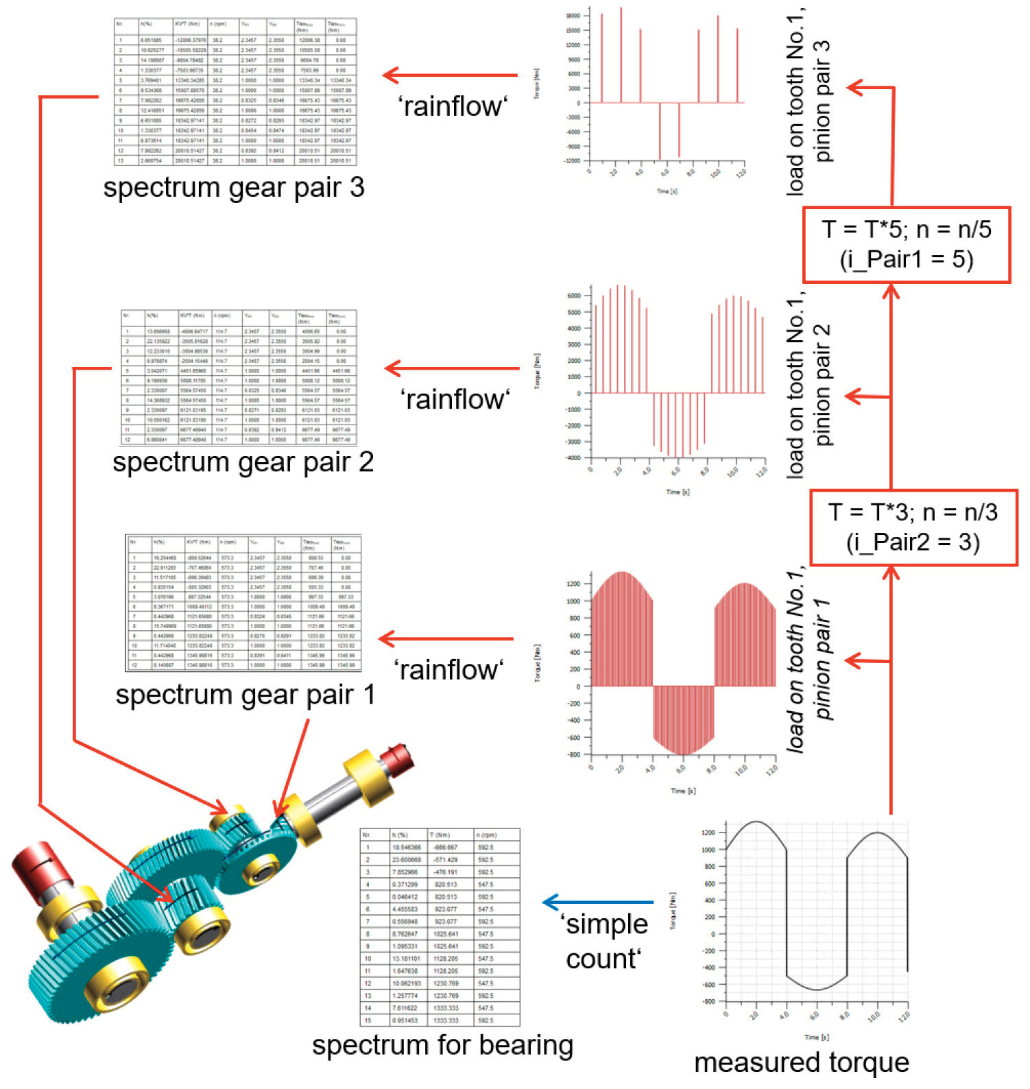
Figure 7—A synthetic time series applied at the input coupling of a three-stage gearbox. The load on an individual tooth of every pinion in the system is extracted from the time series and then converted into a specific load spectrum for every gear stage.
For shafts and bearings alone it is also possible, and simpler, to generate the load spectrum of type A and type B at the position where the time series is applied. Then the system calculation must be executed twice, once with the load spectrum of type A for all the bearing verifications, and then with type B for the shafts.
Use of Time Series for Drive Systems with Different Gear Sets
As mentioned before, the load spectrum in drive system applications must be produced separately for every gear pair when a time series has positive and negative torques/speeds, because the load on the individual gear tooth must be considered for verifications as explained in Figure 1.
Normally the frequency of torque changing from positive to negative, fTorque, is much smaller than the frequency of pinion speed, fSpeed. Let’s assume, that fTorque = 0.25 Hz (torque change every four seconds) and that the pinion speed, first stage, is fSpeed = 10 Hz (600 rpm). In this case, a tooth of the pinion gets, for four seconds, a positive load 40 times, then one load change, then a negative load 40 times. Thus, the load spectrum will contain 2.4 percent of alternating cycles and the rest will be pulsating cycles.
The pinion of the second stage will still get fTorque = 0.25 Hz, but due to the reduction of the first stage (let’s assume as i = 5), the speed will be fSpeed = 2 Hz (120 rpm). The tooth of this pinion gets, for four seconds, a positive load only eight times, then one load change, then a negative load eight times. The load spectrum will contain 11.1 percent of alternating cycles and the rest will be pulsating cycles.
As the alternating load cycles are more damaging than pulsating cycles, the load spectrum in the second stage is different and clearly more damaging than the load spectrum of the first stage (Figure 7).
Application of the Method on a Wind Turbine Gearbox
Figure 8 displays just the first 600 seconds of a time series during the power generation phase of a wind turbine. The torque varies significantly between 146 and 1245 kNm, and the speed is low, nearly constant in the range of 7.0 and 8.6 rpm, also called “cut-in speed.” As the torque is always positive, a gear tooth is always loaded by pulsating stress. Therefore, the simple-count method is used for the generation of the load spectrum for gear and bearing verification. The resulting torque-speed distribution is displayed in Figure 9. The load spectrum contains bins with different torque and speed values. In drive-system software (Ref. 12) the spectrum is attributed to the input coupling (on the turbine shaft) and then automatically adapted and distributed to all elements of the drive system.
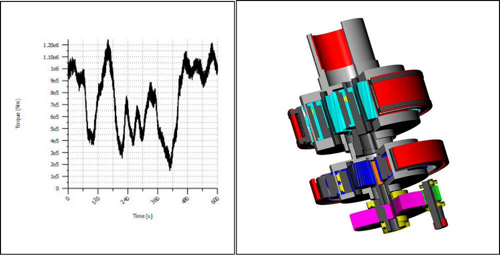
Figure 8—Time series measured during the power generation phase of a wind turbine.
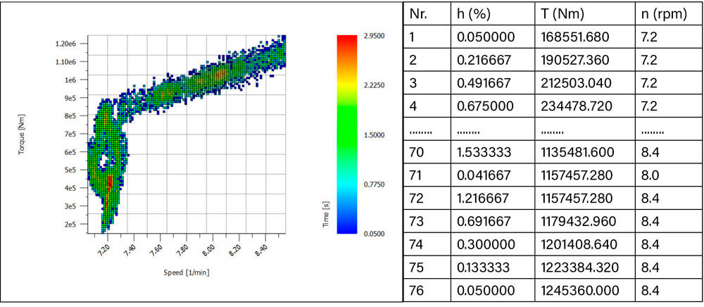
Figure 9—Torque display of the result of the simple-count method, torque-speed distribution with an indication of duration in seconds (left) and the spectrum (right).
For the verification of the shafts, a specific analysis of the number of cycles with bigger amplitudes is recommended. The torque variation (Figure 8) of the time series is generally low, very few times does a change from high to small torque occur. This is also evident in the resume of events shown by the rainflow half-matrix (Figure 10). Therefore, the shaft is not submitted to many significant torsional stress amplitudes. If, as discussed earlier, the torsional stress was assumed to be pulsating, then the resulting safety would be lower. The use of a rainflow analysis provides a more precise result. The obtained load spectrum (Figure 11) is then applied at the input coupling and used for all shaft verifications. For proper verification, critical sections should be designated in every shaft of the gearbox (at positions with shaft shoulders, keyways, etc.) (see Figure 11). The verification is performed for all sections, and the most critical will be found. In the result overview (Figure 12) for every shaft the static and fatigue strength safety in the most critical section is displayed. This, combined with the bending and pitting safety factors for all gear pairs, provides a good overview of the main strength parameters of the wind turbine.
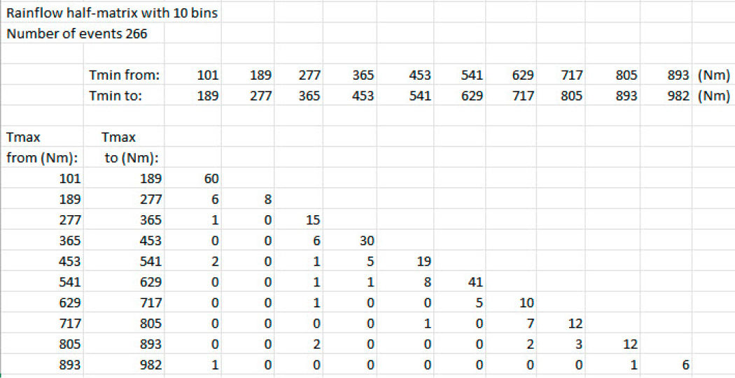
Figure 10—Rainflow half-matrix, most of the 1,512 events (torque changes) found are in the matrix diagonal, where the amplitudes (max-min)/2 are small.
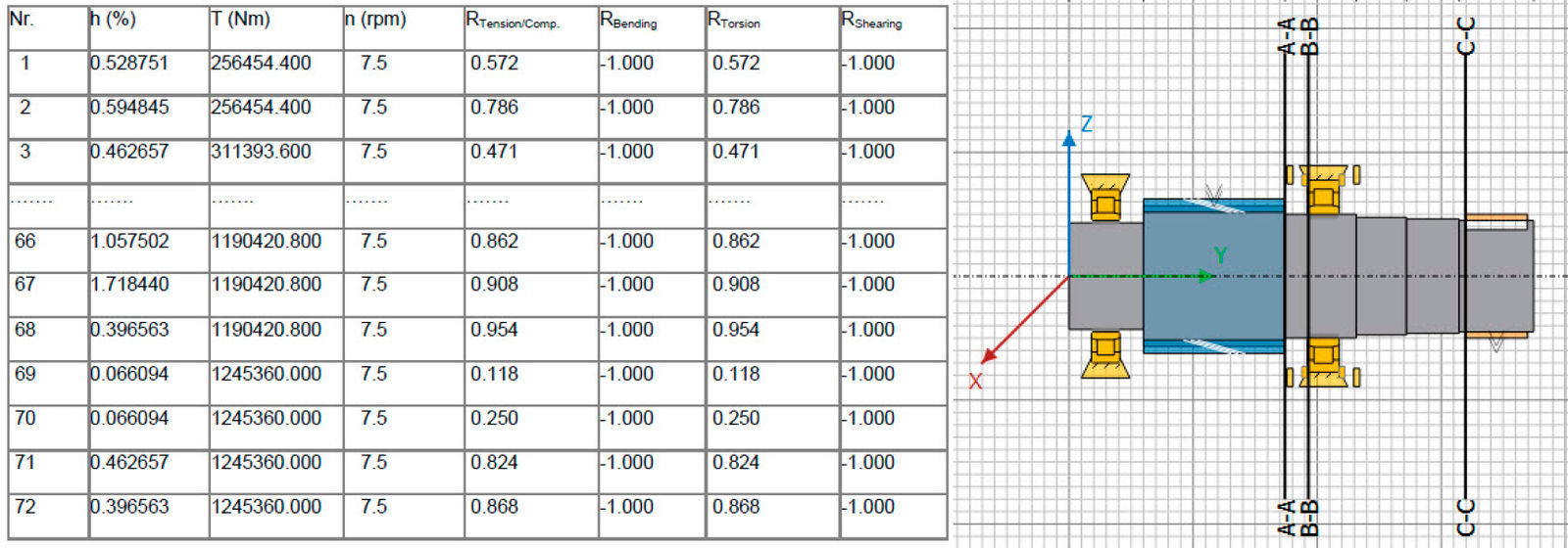
Figure 11—Spectrum for shaft verification (left) and display of the high-speed shaft with an indication of the critical sections (right).
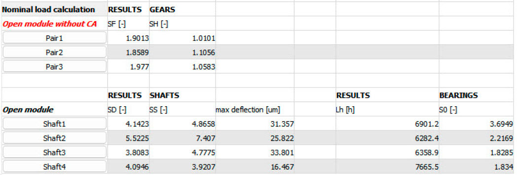
Figure 12—Overview of the results of verifying the wind turbine.
Conclusion
The method discussed is how torque-speed data given at the input or output coupling of a drive system can be converted into a specific load spectrum for the rating of every gear mesh, bearing, and shaft of the system. The procedure differs for these elements, depending on how the load is operating. A gear tooth is submitted to a pulsating load, so, if the torque never becomes negative, no alternating stress happens. A ball of a bearing always gets a pulsating load, regardless of positive or negative torques. A rotating shaft is always submitted to alternating bending stress, but torsional stress amplitudes normally are small when the torque varies slowly (compared to the rotational speed), so often torsional stress is less damaging.
Therefore, the conversion of time series data into a load spectrum is done with different methods for gears, bearings, and shafts; furthermore, the method must be adapted if the torque is changing from positive to negative.
In the second part of the paper, the method of verification with load spectrums for shaft and bearings is explained. These methods are not yet covered by ISO standards, so the verification of bearings is according to literature and the verification of shafts is according to FKM documentation.
References
- Kissling, U., 2021, “Use of duty cycles or measured torque-time data with AGMA ratings,” 21FTM07, Fall Technical Meeting 2021. Also published in Gear Technology, Nov/Dec 2022, pp.48–54.
- ISO 6336-1,2,3:2019, “Calculation of load capacity of spur and helical gears.”
- ISO 6336-6:2019, “Calculation of service life under variable load,”
- AGMA 2001-D04:2004, “Fundamental Rating Factors and Calculation Methods for Involute Spur and Helical Gear Teeth,”
- FKM Guideline, 7th edition, 2020, “Analytical Strength Assessment of Components in Mechanical Engineering,”
- Amzallag, C., Gerey, J.P., Robert, J.L., Bahuaud, J. “Standardization of the rainflow counting method for fatigue analysis,” Int J Fatigue, 1994, Vol. 16, pp. 287–93, https://doi.org/10.1016/0142-1123(94)90343-3
- ISO 12110-2:2013, “Metallic materials—Fatigue testing—Variable amplitude fatigue testing—Part 2: Cycle counting and related data reduction methods.”
- DIN 743-4, 2012, “Calculation of load capacity of shafts and axles—Part 4: Fatigue limit, endurance limit—Equivalently damaging continuous stress.”
- Winter, H.; Niemann, G., 2019, Machine Elements, Vol.1, 5th Edition, ISBN 978-3-662-55482-1, Springer editor.
- https://www.skf.com/group/products/rolling-bearings/principles-of-rolling-bearing-selection/bearing-selection-process/bearing-size/size-selection-based-on-rating-life/bearing-rating-life
- ISO/TS 16281:2008, “Rolling bearings—Methods for calculating the modified reference rating life for universally loaded bearings.”
- KISSsoft gear calculation software, 2023, www.kisssoft.com.
- AGMA 6001-F19, “Design and Selection of Component for Enclosed Gear Drives.”


