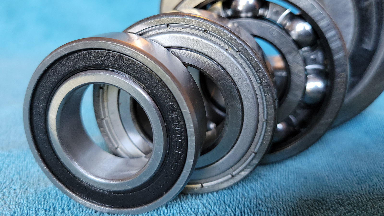
I would like to briefly discuss some thoughts on ball bearing efficiency specifically in terms of applied load and resulting stress. I don’t want to trivialize this subject; there are textbooks written on the subjects of electrohydrodynamic lubrication (EHL), octahedral subsurface shear stress and friction losses due to elastic hysteresis. This is a just a high-level discussion on the importance of individual bearing stress on efficiency.
Why is this important? On some level, I feel like I have, at times, personally concentrated too much on the size of the bearing regarding efficiency. I was trained in the traditional bearing houses with the notion that smaller was always better in terms of efficiency; however, this is not always the case. One of the major sources of energy losses for roller bearings is elastic deformation of the raceway under the loaded rollers. This might also be described as elastic hysteresis: It is the microscopic wave that is generated in front of rolling elements as they pass through the load zone. The higher the load on the individual roller, the larger the loss.
Figure 1—Shear Force Diagram
As you begin to visualize these losses, you may start to wonder if using a smaller premium bearing is truly more efficient than a larger non-premium bearing, considering the individual roller stress will be smaller on a larger bearing.
Of course, there are many factors to consider with a larger bearing that need to be included such as mass, cost, packaging space, transportation costs, ease of installation, etc. but for the purpose of this example, let’s just discuss size vs. efficiency and leave the rest for another day.
As a simple example, I took four ball bearings in the -05 series: a 6005, a 6205, a 6305 and a 6405. I am not suggesting that a 6005 and 6405 would ever be considered interchangeable. This is just for discussion to highlight the differences and get you thinking about stress and efficiency. In the chart below, the four bearings were loaded onto a shaft in MASTA with an external applied radial load. The clearances and fits were all identical: C3 clearance, K5 shaft and H7 housing. The lubrication was a lightweight ATF run at 70°C in an oil circulation system where splash and churning have little effect (churning can be a big factor in oil bath/splash systems). The graph is expressed in terms of percent efficiency over five different applied radial loads.
Efficiency % |
6005 |
6205 |
6305 |
6405 |
Cr |
10.1 |
14 |
20.6 |
36.1 |
Cor |
5.85 |
7.85 |
11.2 |
19.4 |
1 |
99.96 |
99.96 |
99.95 |
99.93 |
2.5 |
99.90 |
99.89 |
99.88 |
99.87 |
5 |
99.74 |
99.71 |
99.72 |
99.72 |
7.5 |
99.52 |
99.47 |
99.5 |
99.53 |
10 |
99.26 |
99.19 |
99.23 |
99.29 |
I highlighted in red dashes the interesting finding in this test. The largest bearing, by far, is the 6405. As we would expect, at low loads, the 6405 is the least efficient. There is a lot of rotating mass, a lot of sliding and overall friction. An interesting change happens around 5kN of applied radial load. At this point, this is around 25 percent of the static load rating of the 6405 but just over 100 percent of the static load rating of the 6005. The percentage of static load can be loosely thought of as stress on the bearing as 100 percent of the static load rating is intended to reach 4,200 MPa of individual Hertzian roller stress. This clearly shows that as the individual stress increases, efficiency decreases. This is not an intuitive exercise because the bearing load ratings are discreet and this essentially turns into a comparison of step functions. A simple example like this might help you get started off on the right foot. Certainly though, in this exercise, a 6305 showing better efficiency than a 6205 might be a surprising finding.
References
- “Using a Friction Model as an Engineering Tool.” Evolution, SKF, 21 Jan. 2020, evolution.skf.com/using friction-model-as-an-engineering-tool-3/.
- Romanowicz, Paweł J., and Bogdan Szybin´ski. “Fatigue Life Assessment of Rolling Bearings Made from AISI 52100 Bearing Steel.” Materials, vol. 12, no. 3, 24 Jan. 2019, p. 371, https://doi.org/10.3390/ma12030371. Accessed 7 July 2022.
- “General Design Information > Cam-Mechanism Design > Design Checks with the Cam-Data FB > Force-Analysis: Cam - Contact-Stress.” Mechdesigner.support, 2024, www.mechdesigner.support/force-analysis-cam-contact-stress-life.htm. Accessed 9 Sept. 2024.