The Art of the Balance
While sitting at a tire shop a while back. I could not help but overhear a customer tell the mechanic he could only afford to pay for the new tires, but not to pay the extra twenty dollars to get them balanced. I thought to myself, “I hope that this mechanic explains that the extra twenty dollars spent to balance is going to save this person hundreds of dollars down the road.” Even vehicle tires require balancing to keep them from vibrating and damaging the other drive train components. In the near future, without balancing the tires, this person is going to be stuck buying all new tires and possibly drivetrain components. The average cost to buy tires today is not exactly cheap. So, when you think about it, the extra twenty dollars to balance is well worth it.
The same goes for impellers and rotors for pumps and motors. Many of us feel that balancing impellers, rotors, etc. is not that important of a procedure. In fact, it is quite the opposite.
Importance of balancing
Impeller and rotor balancing are a crucial part to keeping our pumps and motors running. Why do we balance? There are many reasons that balancing is important, but here are some major ones:- Extended product life
- Increased safety
- Lower operating cost
- Improved performance
- Increased bearing life
- Reduced noise/vibration
- Reduced stress/wear
- Reduced power loss
- Reduced repair cost

Reasons for unbalance
What causes unbalance? Any of the following can cause an unbalance in your rotating equipment:- Design
- Heat
- Assembly errors
- Misalignment
- Flexing
- Density changes
- Nonsymmetry (oval or egg shaped)
- Environmental conditions
- Damage to the impeller
- Bearing Failure
How is balance corrected? This is done by adding material, material removal and shifting of material. Let’s dive in deeper to get a better insight on what types of balancing are applicable to your rotating equipment.
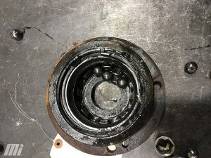
If an impeller or rotor is out of balance, bearing failure can result from the consequential vibration. Vibration is the number one cause of bearing failure. The center of the shaft (or center of gravity) is where the impeller, when it is properly balanced, will want to spin. If it is not properly balanced, the center of gravity will move to the principal axis of inertia, which runs parallel to the center of gravity line. Corrections can be made anywhere on the impeller or rotor, provided the net effect is in line with the rotor’s center of gravity.
Types of unbalance conditions
Static unbalance is the condition in which the central principal axis is displaced only parallel to the shaft axis. For example, a large pulley or an impeller on a single shaft with bearings is considered static unbalance.Dynamic unbalance is the condition in which the central principal axis is not parallel to and does not intersect the shaft axis. For example, a rotor out of an electric motor or a split-case impeller assembly is considered dynamic unbalance.
Couple unbalance is the condition in which the central principal axis intersects the shaft axis at the center of gravity. For example, a railroad wheel assembly is considered couple unbalance.
Quasi-static unbalance is the condition of the unbalance for which the central principal axis intersects the shaft axis at a point other than the center of gravity. For example, a great scenario for quasi-static unbalance is an electric motor and blower wheel assembly.
The two main types of balancing on rotating equipment are static and dynamic. How do we determine what type of balance procedure must be done for the correct application? Most impellers will be static balanced to a G-6.3 per ISO 21940-11 standard, and rotors will be balanced to the same standard as impellers. We determine static balance by focusing on the impeller itself and nothing coupled to it (shaft, bearings, etc.). That is due to the impeller being larger/heavier than the bearings. That is when you will want to static balance.
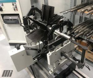
The best scenario to dynamically balance would be rotors that go in a motor because there is equal weight on both sides. Rotors can also be classified as couple unbalance. In addition, on each side of a rotor shaft will be the bearings that the rotor will spin. You will also want to dynamically balance a split-case impeller assembly (the shaft is coupled on both sides by bearings and bearing housings) for the same reason. It acts almost identically to rotors in terms of how they operate.
When dynamic balancing, you will be removing/adding material on either side of the rotor/impeller to create equal balance on both sides. This will create smooth operation with vibration being almost nonexistent. It will also increase performance, as the rotor/impeller will spin without straining the bearings. With less strain, you will have minimal power loss when it comes to an impeller under a load. Loads on impellers consist mainly of water pressure fluctuations. A load on a rotor will consist of a blower attachment or fan to help cool the motor down. However, the main cause of stress on a rotor is vibration. If the rotor cannot spin freely without vibration, you will experience power loss as the rotor will not be able to output the torque needed to operate whatever it is coupled to.
Balance for Maximum Performance

For more information, visit Motion.com.


