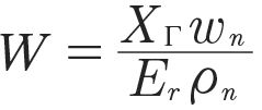
 (4)
(4)
Where
a = pressure-viscosity coefficient
hM = dynamic viscosity at gear tooth temperature
Er = reduced modulus of elasticity
oe = entrainment velocity
XC = load sharing factor
wn = normal unit load
tn = normal relative radius of curvature
For a given gear set, the material elasticity Er, entrainment speed oe, geometry tn, load sharing factor XC, and load wn, can be considered constants. Therefore, the EHL film thickness equation reduces to:

(5)
Where
C = gear set constant (includes Er, oe, tn, XC, and wn)
a = pressure-viscosity coefficient
hM = dynamic viscosity at gear tooth temperature
The value of constant C is independent of the lubricant and depends solely on the properties of the gear set.
Baseline Film Thickness
The gear set baseline EHL film thickness is:

(6)
Relative EHL Film Thickness
The relative EHL film thickness is defined by:

(7)
The constant C in the numerator and denominator of Equation 7 cancel, and the relative EHL film thickness equation reduces to:

(8)
Therefore, the relative EHL thickness is normalized and dimensionless, and can be calculated without regard to the fixed parameters included in the constant C of the gear set.
The baseline parameters abase and hMbase can have arbitrary fixed values. For example, Table 1 shows the baseline parameters for ISO VG 320 mineral oil arbitrarily chosen at 80°C are abase = 0.017246 and hMbase = 40.49869. With these baseline values Equation 8 becomes:

(9)
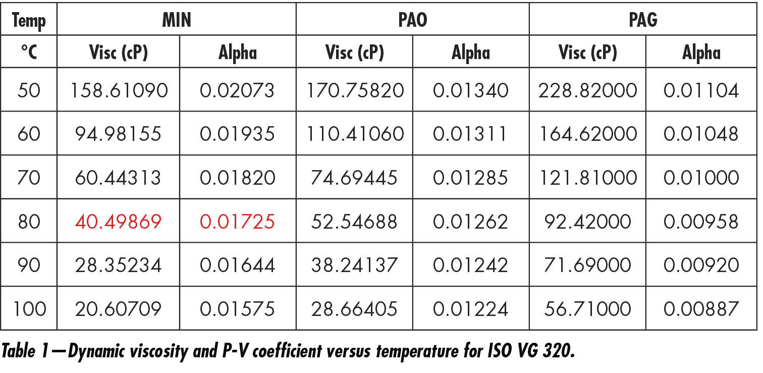
Equation 9 differentiates the film forming behavior of various lubricants because it accounts for differences in a and hM. Applying Equation 9 to the Table 1 values gives the relative EHL film thickness values shown in Table 2. Figure 1 is a graph of the Table 2 values.
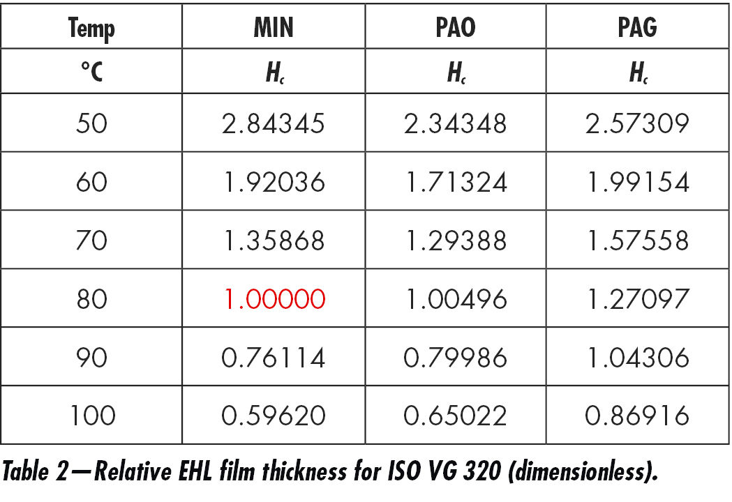
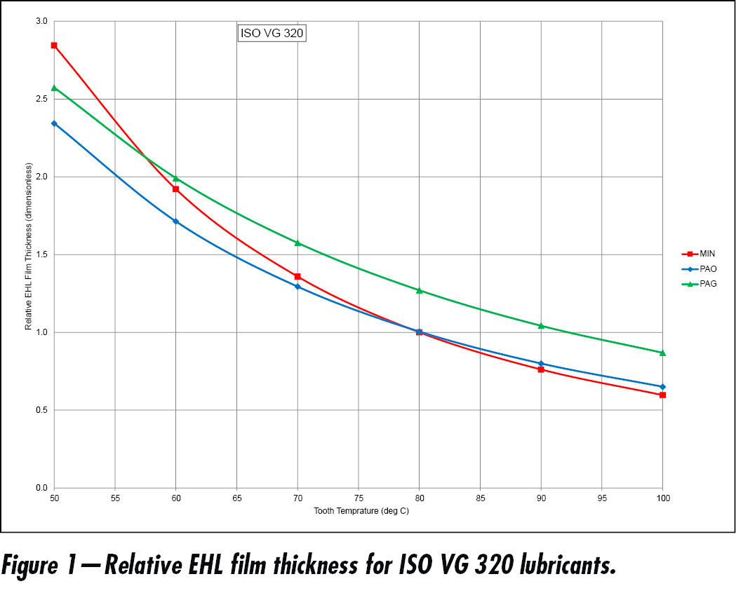
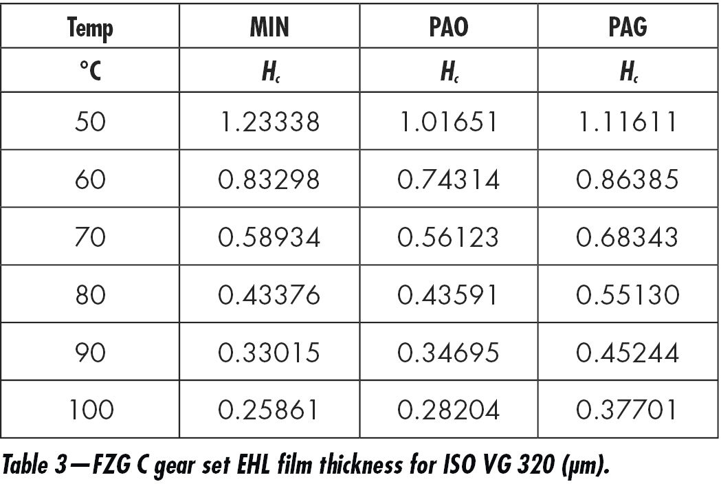
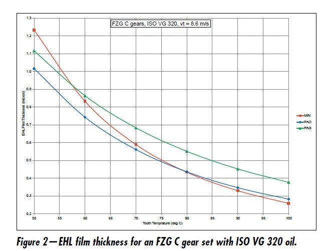
All that is necessary for converting Table 2 to actual film thickness values in microns is to calculate the EHL film thickness for the gear set with a mineral oil at the baseline temperature of 80°C and baseline values of abase = 0.017246 and hMbase = 40.49869, and then multiplying the Table 2 values by the EHL film thickness obtained for the gear set at the baseline values. For example, EHL film thickness for an FZG C gear set with ISO VG 320 MIN at the baseline values is Hc = 0.43376 µm. Multiplying Table 2 values by 0.43376 gives the Table 3 values. Figure 2 is a graph of the Table 3 values.
Influence of ISO VG
Conclusions
- The relative EHL film thickness is normalized and dimensionless, and it can be calculated without regard to the parameters of the gear set.
- Equation 8 gives the relative EHL film thickness for a given ISO VG, several lubricant types, and range of temperature.
- The relative EHL film thickness is normalized to an arbitrary baseline consisting of a lubricant type, ISO VG, and baseline values of temperature, dynamic viscosity, and pressure-viscosity coefficient.
- The actual range of EHL film thicknesses for a given gear set can be obtained from a single calculation of EHL film thickness for the gear set by assuming the baseline values of a lubricant type, ISO VG, tooth temperature, dynamic viscosity, and pressure-viscosity coefficient, and then multiplying the calculated gear set EHL film thickness by the relative EHL film thickness.
- The graph of relative EHL film thickness is the same as the graph of actual EHL film thickness except for units of the ordinate (dimensionless versus µm).
- Relative EHL film thickness varies with ISO VG.
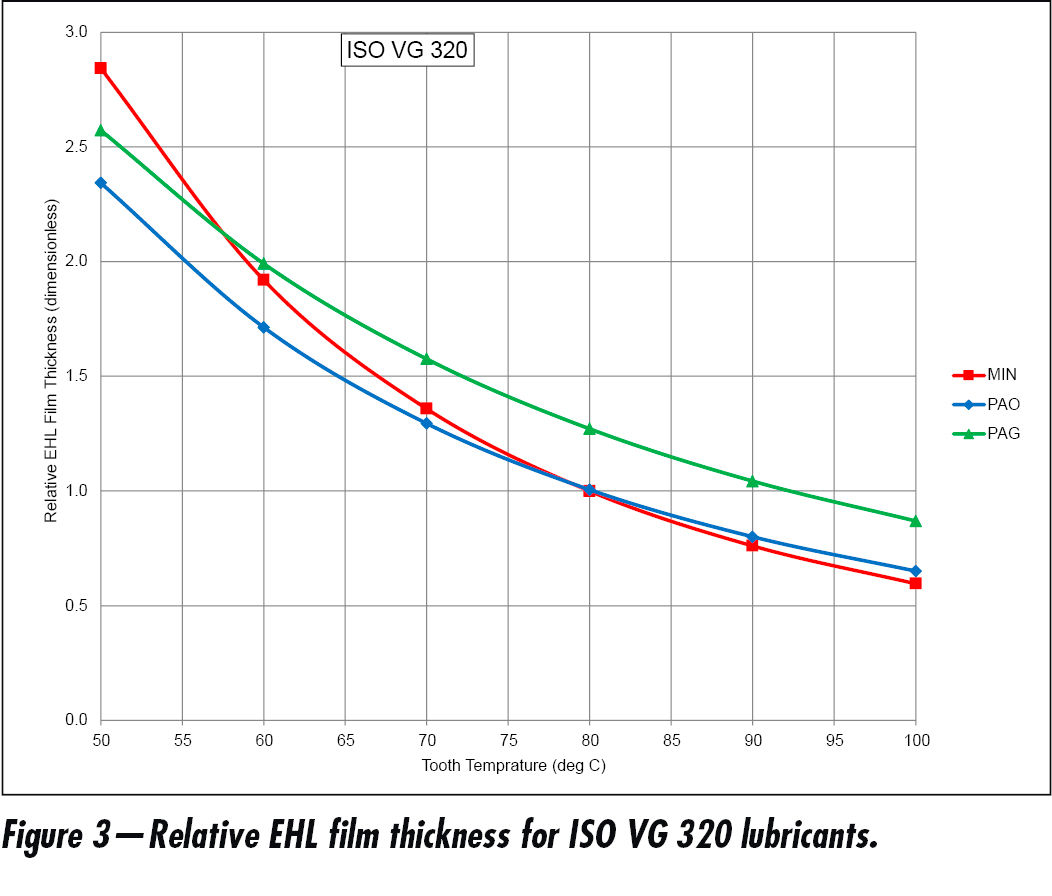
- Figure 3 compares performance of the three ISO VG 320 lubricants:
- MIN outperforms PAO at temperatures ≤ 80°C.
- MIN outperforms PAG at temperatures ≤ 58°C.
- PAG outperforms MIN at temperatures ≥ 58°C.
- PAG outperforms PAO at all temperatures.
- MIN and PA0 perform similarly at temperatures ≥ 80°C.
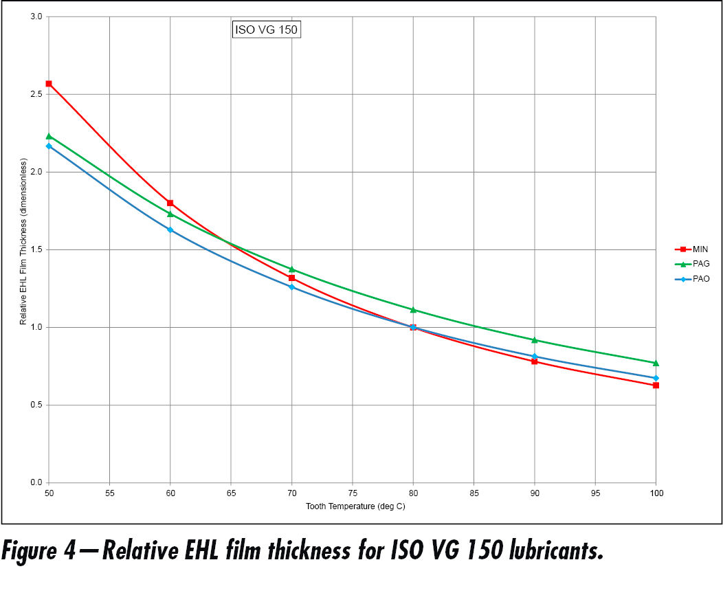
- Figure 4 compares performance of the three ISO VG 150 lubricants:
- MIN outperforms PAO at temperatures ≤ 80°C.
- MIN outperforms PAG at temperatures ≤ 65°C.
- PAG outperforms MIN at temperatures ≥ 65°C.
- PAG outperforms PAO at all temperatures.
- MIN and PA0 perform similarly at temperatures ≥ 80°C.
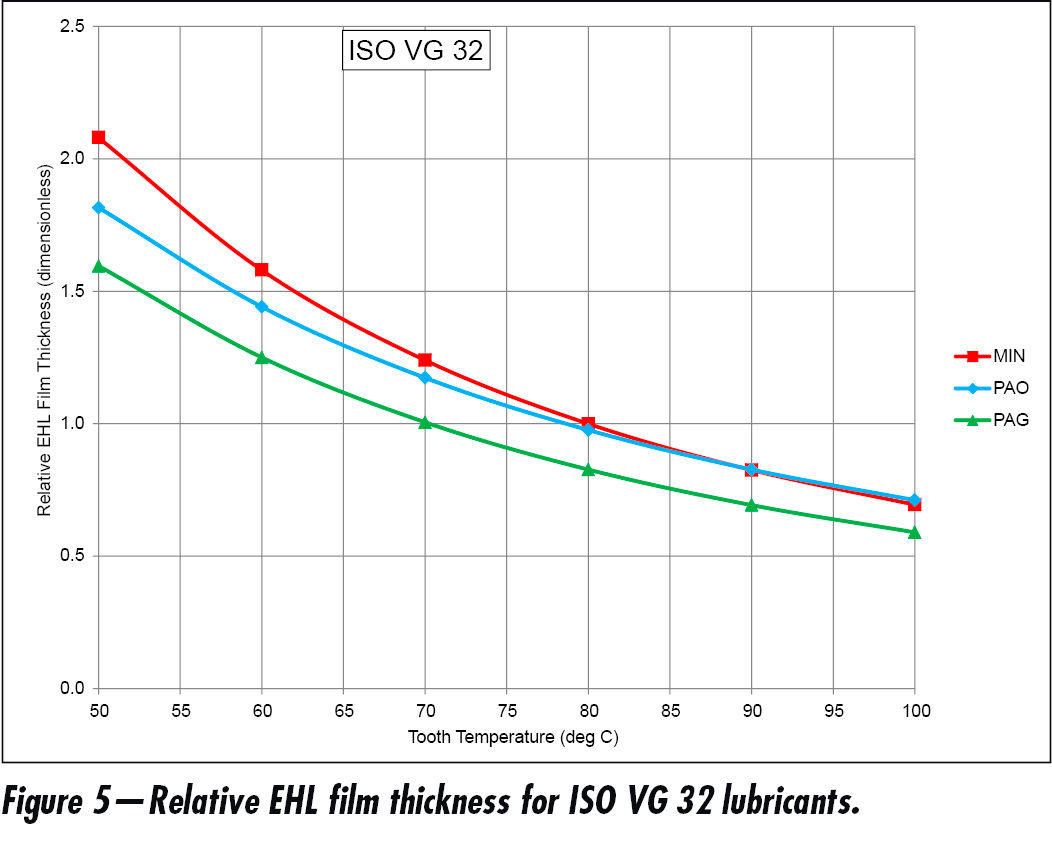
- Figure 5 compares performance of the three ISO VG 32 lubricants:
- MIN outperforms PAO at temperatures ≤ 90°C.
- MIN outperforms PAG at all temperatures.
- PAO outperforms PAG at all temperatures.
- MIN and PAO outperform PAG at all temperatures.
- MIN and PA0 perform similarly at temperatures ≥ 90°C.
References
- GEARTECH Report No. 2038, “Comparison of EHL Film Thickness versus Temperature Characteristics of Mineral, PAO, and PAG Lubricants,” Prepared for NREL under subcontract No. EXL-8-1749701, May 31, 2002, pp. 1-9.
- AGMA 925-B22, “Effect of Tribology and Lubrication on Gear Surface Distress,” April, 2022.


 (4)
(4)


