System Design Options
Systems using variable speed pump
drives can use a number of different
design solutions. The selection of the
design solution depends on a number
of factors. The type of hydraulic circuit,
the required response times and accuracy,
the power required and other factors
all come into play when deciding
the best drive and circuit design.
Dynamic performance and power
requirements determine the choice of
the motor. For applications requiring
the fastest response times and highest
accuracies, a PMM may be the best selection.
Today this technology is used
extensively in plastic injection molding
machines. These drive systems offer
extremely high performance and have
high productivity rates.
Due to their high power density and
low drive inertia, PMMs have the highest acceleration capabilities. These high
dynamics allow complex machine control
tasks, such as direct force, speed
and cylinder position control to be realized
without proportional valves. The
main limitation when using PMMs is
maximum continuous output power
— typically less than 60kW. Power
units with higher output power, greater
than 60kW, may require multiple PMMpump
groups.
Standard asynchronous induction
motors driven with VFDs can be used
in higher power applications, or where
direct control of high dynamic axes is
not required. Using standard induction
motors with VFDs, operating in a sensor-
less vector control mode (no separate
motor feedback device required),
results in a cost-effective system. However,
the system designer should be
aware of the limitations of direct control
using these drives.
The system response times can be
long as a result of the high inertia of the
induction motor. Variable speed pump
drives using standard induction motors
with VFDs are used today in the
woodworking industry, on press applications,
in plastics machinery, heavy
industry applications and machining
tool applications where the control task
is typically regulating system pressure
or flow.
Selecting Motor Size
The motor size and drive should be selected
based on the pressure-flow-time
cycle (p/Q profile) for the application
machine. In practice, motors on standard
HPUs are often sized on “corner
power,” calculated from the maximum
pump pressure and flow, and duty cycle
is commonly not taken into account.
This results in the installation of excess
motor HP. If partial load comprises
a significant portion of the machine
cycle, the excess motor power can be
significant.
Sizing PMMs for variable speed
pump drives should follow methods
commonly used in electromechanical
actuator drives; calculating the root
mean square (RMS) value based on the
load torque and average drive speed.
Once a pump size is determined, the
motor torque and speed are calculated
from the required pump pressure and
flow. Additionally, the dynamic torque
requirements for accelerating and decelerating
the motor’s rotor and pump
inertia needs to be added.
These calculated values are used to
select the proper size drive and motor.
Drive sizing and system optimization
can be done using specialized tools,
such as Bosch Rexroth’s SytronixSize,
which allows analyzing p/Q profiles
and motor load factors. For a more
complex analysis, a numerical simulation
can be used to model the system.

Figure 4 Using VFDs with hydraulic power units can lower average noise emissions. Since the pump
speed is reduced during partial load operations, average sound levels can be reduced by as
much as 10-20 db (A).
Dynamic simulations help by providing
more insight to the system dynamics,
such as pressurization dynamics,
and to investigate interactions between
the drive and the hydraulic system.
Analysis of the performance of closedloop
controls can be done as well. These
dynamic simulations can be carried out
using software that includes drive- and
hydraulics-model libraries. Simulation
tools, such as Bosch Rexroth’s Simster 3,
ITI SimulationX or MATLAB/Simulink
Simscape can be used for these requirements.
Pump Selection Criteria
When selecting the pump for variable
speed operation, several important factors
must be considered:
- Is the pump construction suitable for
variable speed operation?
- What are the minimum- and
maximum-allowed RPMs for the
pump?
- Can the pump be used bidirectionally,
and if so, are there any
pressure and speed limitations?
- Is the pump suitable for start and
stop operation?
- What is the maximum operating
pressure allowed for the pump, and
does pressure affect the maximumallowable
pump speed?
- What fluid will be used in the system
and does it limit the pump’s pressure
and speed, based on viscosity and
pump lubrication?
- What is the mechanical and
volumetric efficiency of the pump at
the design operating points?
- Consider pump acoustic noise
level — based on expected speed,
pressure, and displacement.
- What will be the pressure and
flow pulsations over the range of
operating speeds?
- Is the hydraulic circuit of open or
closed type?
Improper pump selection or operation
beyond allowed conditions can result
in premature pump failure or suboptimal
control performance. Pumps
used with speed variable drives are
typically internal gear or piston pumps.
In some cases, properly selected vane
pumps may also be used.

Figure 5 In recent years the cost of using variable-speed drive technology has become more
economical, making it effective to combine variable-speed electric drives with hydraulics to
provide an energy-saving, high-performance alternative for use in many applications.
Internal gear pumps are characterized
by high-efficiency, low-flow ripple,
low-mechanical inertia and high-pressure
capability. Due to these characteristics they are widely used with PMMs
on injection molding machines. The
limitations are fixed displacement and
limits on the minimum drive speed
during pressure holding operation.
Axial piston pumps, of either fixed
or variable displacement design, have
the desired property of high efficiency
at low speed, making them ideal for
pressure holding operation. Using a
variable displacement pump allows
the possibility of reducing the motor
torque during pressure holding in
the machine cycle. This can result in
higher system efficiency since the motor
and pump can operate under more
desirable conditions. High-response
variable displacement pumps, such as
Rexroth’s DFEn 5000, can have reaction
times an order of magnitude faster
than a VFD- driven induction motor.
Combining this pump with a VFDcontrolled,
induction motor, results in
greater efficiency and much higher system
response than a sole variable speed
alone; it is of greater value when used
with higher HP-drive motors.
It is expected that in the future speedvariable
pump drives will replace an increasing
number of standard motors in
hydraulic power units. This change is already
utilized by many plastic machinery
OEMs, and is quickly expanding in
press applications. Understanding the
principles of variable speed drives and
the interaction between hydraulics and
electric drives will be key to future fluid
power engineering.
 Paul Stavrou
 possesses 39
years’ experience in the fluid
power industry — working
in marketing, engineering
and development for electrohydraulic
components and
systems. He holds a degree in
electrical engineering from
Lehigh University and three patents for electronic
control systems. Stavrou is manager of system
applications at Bosch Rexroth Corporation in
Bethlehem, PA.
Article reprinted courtesy of the Bosch-Rexroth Corporation.


 Figure 1 The newest generation of hydraulics technology, such as Rexroth’s Sytronix variable speed
pump drive system, integrates powerful, energy-efficient hydraulic pumps with advanced,
intelligent electronics and controls.
Figure 1 The newest generation of hydraulics technology, such as Rexroth’s Sytronix variable speed
pump drive system, integrates powerful, energy-efficient hydraulic pumps with advanced,
intelligent electronics and controls.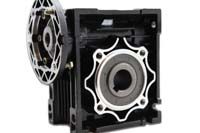 Figure 2 Shown is power consumption, in a dead-head condition, for a 125cc axial piston pump
driven by a 100 HP premium efficiency motor. The energy used is considerably lower when
using a VFD, as compared to a constant speed drive.
Figure 2 Shown is power consumption, in a dead-head condition, for a 125cc axial piston pump
driven by a 100 HP premium efficiency motor. The energy used is considerably lower when
using a VFD, as compared to a constant speed drive.
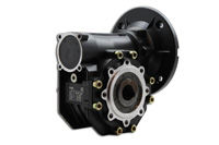 Figure 3 The Sytronix DFEn variable speed pump combines high dynamics and high power output for
pressure, flow and power control applications.
Figure 3 The Sytronix DFEn variable speed pump combines high dynamics and high power output for
pressure, flow and power control applications.
