

Motors without Rare Magnets: What are the Options? (Part Two)
In Part I we explored various motor technologies used today for industrial and traction motor design. Here in Part II we will explore another motor option: reluctance motors.
Although invented in the 1800s, the variable switched reluctance (VSR or SR) motor was re-discovered in the 1990s when the electronic power switches, FETs, IGBTs, became readily available on a commercial basis. In recent years the VSR has once again attracted a lot of attention as a cost-effective alternative to the permanent magnet (PM) motor.
The VSR has a number of rotor and stator teeth where the number of rotor teeth nr is typically +/- 2 of the number of stator teeth ns, and ns is an integer multiple of 2 times the number of phases np. The VSR is characterized by its ratio of rotor-to-stator teeth and common ratios are 6/4 and 12/8 for a 3-phase motor and 8/6 for a 4-phase motor.

The VSR motor can be very efficient; for example, a 5 KW VSR motor can reach up to 95% efficiency. And a larger VSR motor can have even higher efficiency. The VSR delivers constant torque — from starting torque up to a “base” speed — and the constant power above up to 3x the base speed without a significant loss in efficiency. The speed/torque curve of a typical VSR motor is shown (Fig. 3, top of the blog).

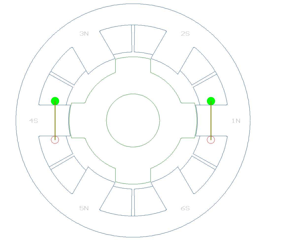
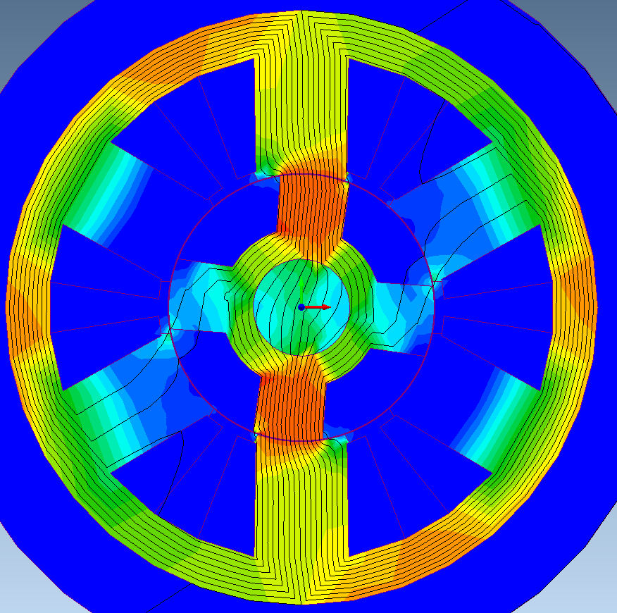
The main drawback of the VSR motor is that each of its phases must be controlled independently — which requires two motor leads to be brought out from the motor to the controller for each phase — and the controller requires additional components, compared to a permanent magnet (PM) brushless motor (BL). In Figure 5 we show the flux pattern of a typical VSR lamination.
Also, the airgap of the VSR is small, i.e. 10 – 20 mils — which presents mechanical challenges — and it results in strong, radial magnetic forces acting on the rotor. These forces, coupled with the thin outer lamination ring, result in acoustical noise that is generated in the VSR motor; so they can be noisy unless additional design measures are taken.
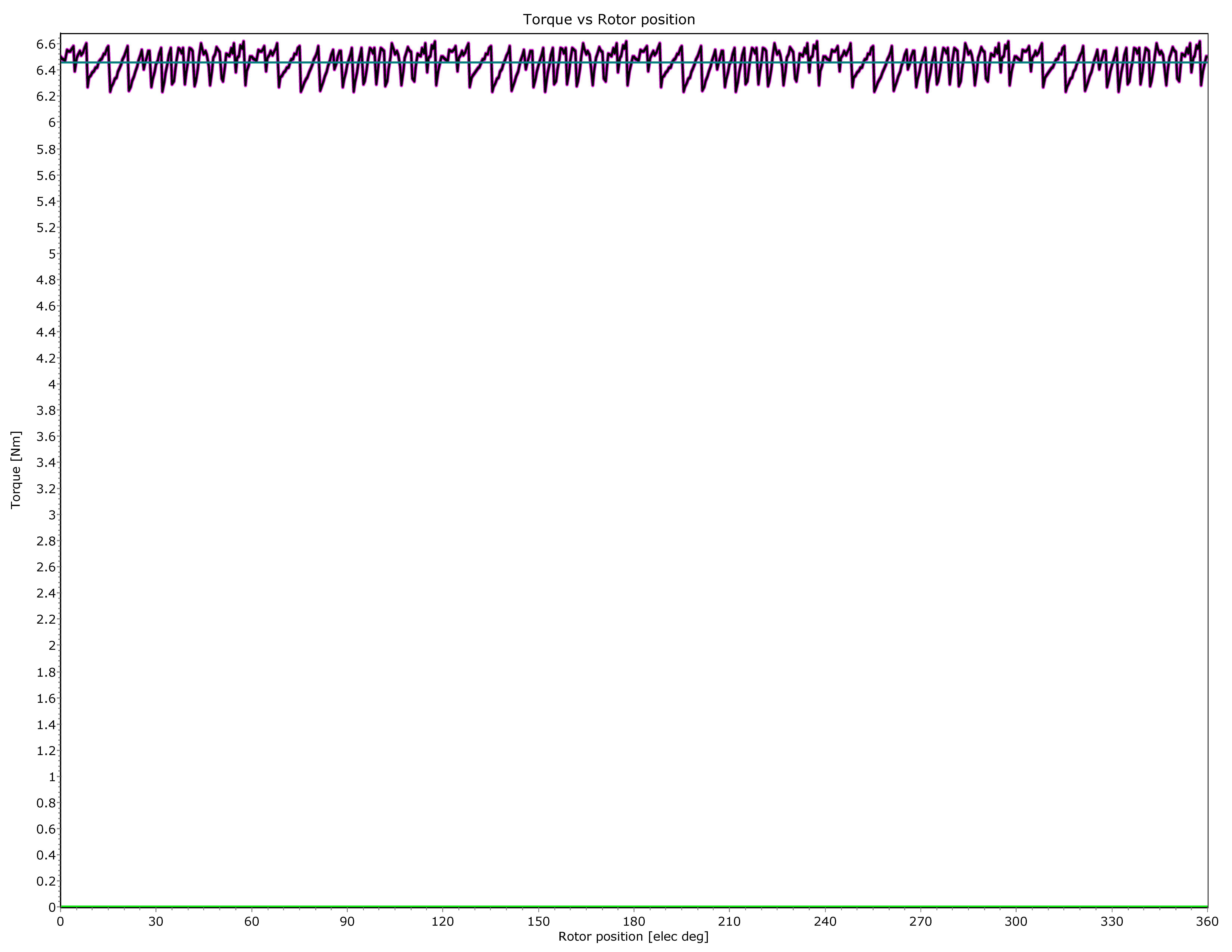
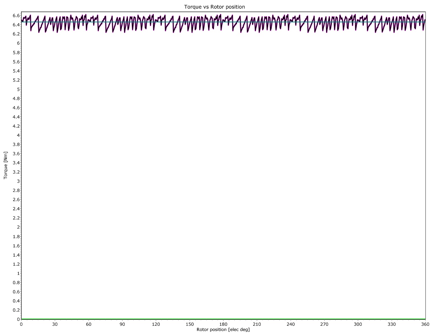
An additional concern typically associated with VSR motors is the torque ripple, as shown in Figure 6.

However, there is a second type of reluctance motor which, until recently, did not gain much attention, i.e. — the synchronous reluctance motor (SYR) — and it has only recently generated serious interest.
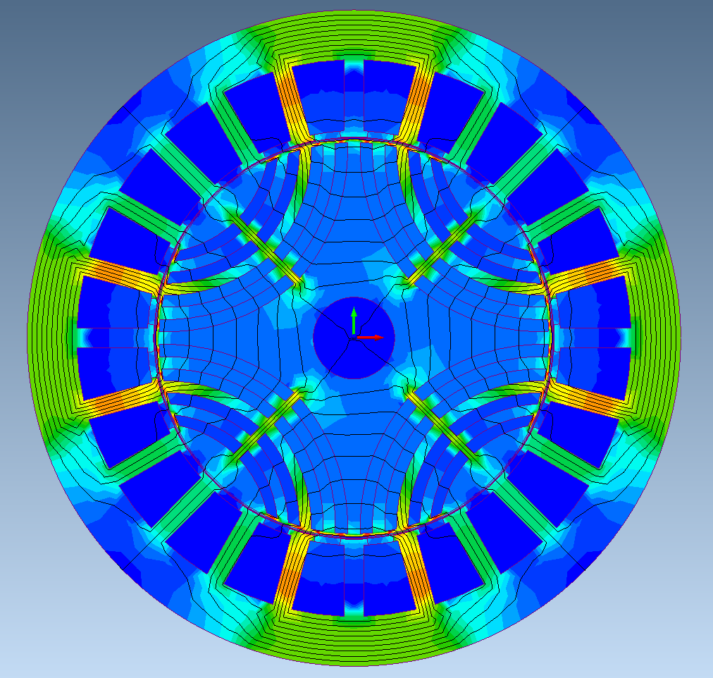
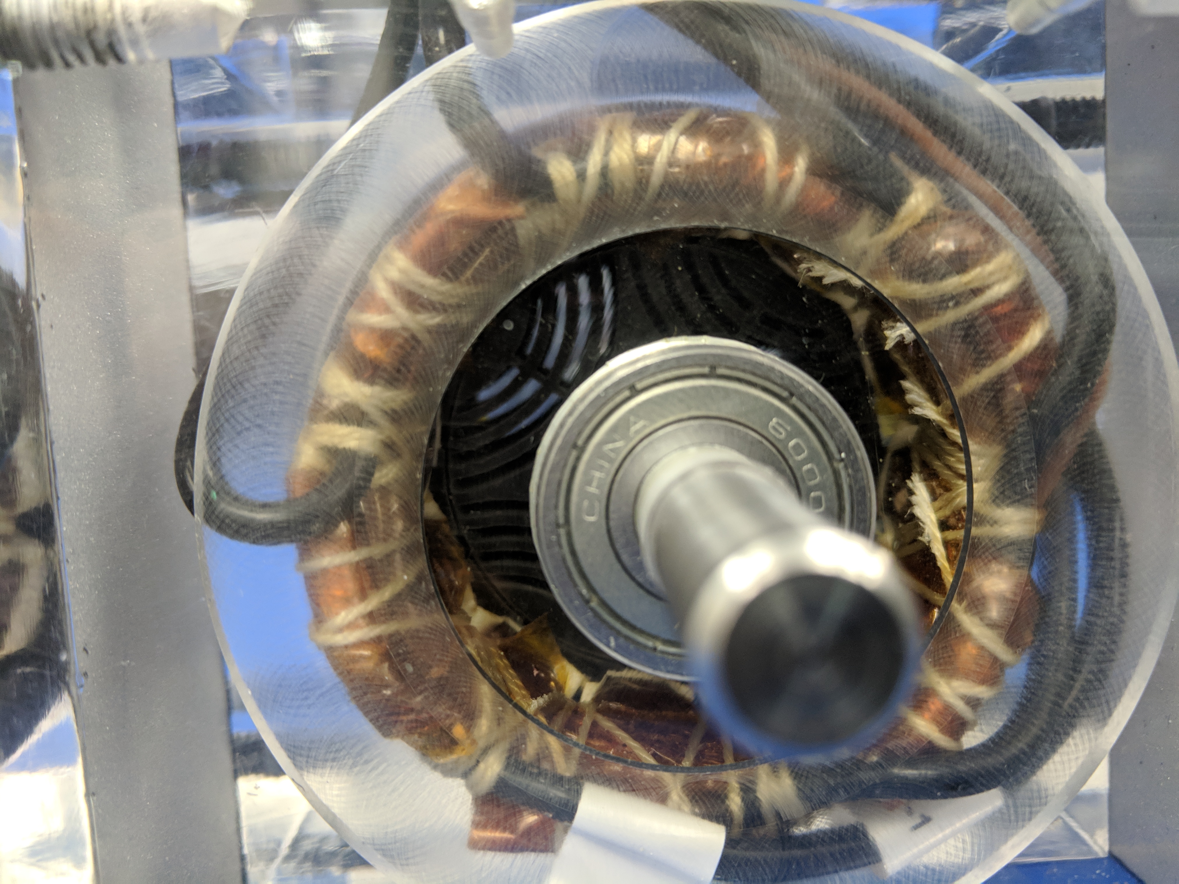
Figure 7 shows the lamination design of a synchronous reluctance motor and Figure 8 shows the flux distribution in the SYR lamination; and in Figure 9 is a photo of a SYR motor.

The SYR can be manufactured with the same winding equipment and facilities as existing brushless and induction motors. No magnets need to be glued and/or retained, which further simplifies SYR manufacturing and results in cost savings.
Like the PM brushless and the ACI, the SYR requires one motor lead per phase and, with minor software changes, it can run with the same controller hardware as the PM brushless motor.
Because the stator backiron is generally thicker than that of the VSR motor, the SYR runs quieter. Testing on some motor comparisons has shown that the SYR has a noise signature that is comparable to that of a PM BL motor in specific applications.
The operating efficiencies of the SYR motor are slightly less than those of a high-performance neodymium PM BL, but that is offset by a lower manufacturing cost for the motor and a significant lower controller cost.
Also, while the SYR will have its highest operating efficiencies when excited with sinusoidal waveforms (AC), the SYR will also perform very efficiently when energized with trapezoidal waveforms — just like the brushless DC motor. This allows for low-cost Hall sensors to be used for feedback. Both the VSR and SYR can be operated sensor-less, using proprietary sensorless controls for positioning and speed control of SYR motors without loss in performance for high-temperature automotive and military applications.
Also, since the SYR motor has no magnets, its rotor can run hotter and there is no risk of demagnetization during overload conditions — a key feature for some advanced automotive and military applications.
In Table 1 we show a comparison of material weights: one component in the cost comparison used when deciding which motor to use.
Table 1 Comparison of material weights.
| PM brushless | VSR | SYR | |
| Laminations (lb) | 0.48 | 0.53 | 0.42 |
| Copper (lb) | 0.22 | 0.28 | 0.16 |
| Magnet (lb) | |||
| Magnet Assembly | 2.75 | 0.00 | 0.00 |
| Shaft | 1.50 | 1.50 | 1.50 |
| Bearings | 2.00 | 2.00 | 2.00 |
| Endbells | |||
| Housing | |||
| Assembly | |||
| Lamination $/lb | 2.00 | 3.00 | 3.00 |
| Copper $/lb | 10.00 | 10.00 | 10.00 |
| Magnet $/lb | 5.60 | ||
| Total Cost | 9.41 | 7.88 | 6.35 |
This comparison clearly favors the SYR in this specific example and, if the controller cost were taken into account, the SYR and the PM brushless will be the prime candidates. Potential customers have been quite receptive, and working designs are being sought to replace offshore PM BL motors with SYRs that can be cost-effectively produced domestically.
Next time you need a low-cost, high-performance motor, you should look beyond the PM BL motors and consider the reluctance motors — specifically the SYR — as an alternative to a lower-cost motor drive system.
For more information contact the author at Rocky Mountain Technologies at 406-225-7120 or info@RockyMountainTechnologies.com
This article first appeared in the 2019 December issue of PTE:
https://www.powertransmission.com/issues/1219/motors.pdf
