Mitigation of Gear Whine Noise in Agricultural Tractor Application
In the realm of tractor gearbox applications, gear whine noise has long been a persistent challenge that significantly impacts the user experience and overall perceived performance of the vehicle. This paper delves into a comprehensive study that discusses the approach to tackling this issue through a combination of design optimizations, simulation techniques and physical validation processes.
The study begins by meticulously examining the load-dependent noise characteristics encountered during field operations, where distinct gear orders were observed prominently at given speed conditions in the noise order analysis. After conducting extensive drivetrain simulations, the research shifts its focus towards optimizing the gear tooth macro geometry, with specific emphasis on increasing the total contact ratio (helix angle and face width), while also incorporating refinements to the gear micro geometry within the confines of design and manufacturing constraints.
Moreover, the study delves into addressing gear manufacturing variations by transitioning from conventional shaving processes to tooth grinding methods, thereby effectively controlling the gear tooth profiles. To further validate the simulation model, a system-level bench test is conducted utilizing a gear contact pattern correlation approach.
Additionally, the research endeavors to develop prototype gears to facilitate physical experimentation, employing multiple parameter combinations to validate the proposed modifications. The culmination of these interventions results in a significant reduction in Operator Ear Noise Level (OENL), underscoring the efficacy of this comprehensive approach in analyzing and mitigating gear whine noise in real-world tractor applications.
This study underscores the critical importance of meticulous geometric modifications in effectively addressing and minimizing gear whine noise, ultimately contributing to an enhanced overall tractor performance and improved user experience.
Problem Statement
During the field testing of the new tractor transmission development project, gear noise was reported in a plowing application. Test data analysis was carried out to locate sources in the specific application, engine RPM range and gear engaged. Sound recordings reported by field test engineers revealed that this noise was tonal in character. The OENL was reviewed by the project team and was found to be unacceptable. A team was formed to work on the issue resolution. The objective was derived to reduce noise to an acceptable level. A multidisciplinary team was formed to address this issue which included team members from drivetrain design engineering, virtual verification, component bench testing, field testing, Noise, Vibration & Harshness (NVH) testing, prototyping, and manufacturing quality.
In a study by Liu et al. (Ref. 1), the impact of profile and face contact ratios on gear mesh stiffness and gear whine noise in helical gears was investigated. The research highlighted that while the total contact ratio should not be an integer, a face contact ratio close to an integer can help minimize noise. This study provided valuable insights into target contact ratios, moving away from the conventional “more is better” approach.
Munro and Houser (Ref. 2) outlined various gear noise excitations, including transmission error, mesh stiffness variations, axial shuttling, friction, and entrapment of oil or air. Post-test examinations ruled out flank friction and air entrapment as factors, and the absence of burnt oil traces eliminated oil entrapment as a parameter of interest. The study delves into the remaining factors later in this paper.
Lahoti, Patil, and Wagner (Ref. 3) emphasized the benefits of reducing transmission error and improving contact patterns to reduce gear whine noise. Their work demonstrated a strong correlation between reducing transmission error and minimizing noise, stressing the importance of analyzing these enhancements across the application load spectrum for consistent noise performance.
The work of Smith et al. (Refs. 5, 6) addressed the necessity and design considerations of tip reliefs, distinguishing between “short” and “long” tip reliefs and their respective applications.
This research integrates insights from these studies and applies them to a real-world gearbox noise issue. The paper also incorporates manufacturing trials to validate assumptions made in design and simulation, followed by testing and physical validation of the proposed solution.
Gear Drive Schematic and Nomenclature
Part of the gearing arrangement in said geartrain is shown in Figure 1.
Figure 1—Gearbox schematic and power flow.
The three gear meshes shown here carry torque through the transmission in given gear and range shift lever positions. The gear meshes of interest are Gear mesh 1 (18.75 order of input shaft) and Gear mesh 2 (15.1 order of input shaft). The red arrows mark the direction of torque flowing through this multi-axis gearing system.
Methodology
Noise Testing and Order Analysis for Source Identification
Noise data is recorded using a binaural headset along with engine RPM. Different sets of data acquisition were executed corresponding to constant RPMs, engine RPM sweep (from low idle to high idle engine RPM). A sampling rate of 44 kHz is considered. For test data analysis, a frequency resolution of 1 Hz with A-weighting is applied.
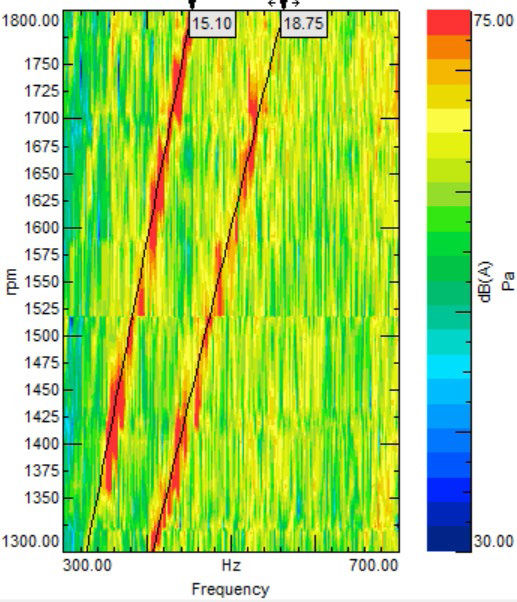
Based on the order analysis, high amplitude orders were identified as shown in Fig. 2. By suppressing those orders in sequence/combination and listening to the sound, dominant orders 15.1 and 18.75 are confirmed for further investigation.
Figure 2—Baseline response.
[advertisement]
The noise was specific to the combination of the speed and range lever selection. In the noisy condition, three gear meshes were transmitting torque to the spiral bevel gears connected to the rear axle through the planetary final drive. Based on the number of teeth and power flow, orders were calculated for different gear mesh combinations. It was found that the two identified orders viz 18.75 and 15.1 corresponded to one range gear mesh and one-speed gear mesh which were engaged and transmitted the torque.
Gear Geometric Parameter Considerations and Virtual Analysis
Gear Macrogeometry Improvements
To increase the profile contact ratio in each gear mesh, the modules were reduced, and tip diameters were increased marginally. To prevent contact between the tip and the root of the gear, we first performed theoretical calculations to determine the necessary root clearances. In addition to these manual calculations, we also used advanced simulation software to analyze potential tip-to-root contacts. This analysis considered factors such as increased tip diameters, misalignments, and tooth deflections. The macro geometry improvements also included, in each gear mesh, the gear face width and helix angle increase to achieve a minimum face contact ratio of 1. These design enhancements helped raise the sum of contact ratios to over 2.5 for these helical gears. A summary of these changes is provided in Table 1. These macro geometry changes were in line with the study by Liu et al. (Ref. 1) mentioned earlier.
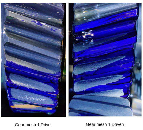
To calibrate the simulation model, a gear contact pattern test was conducted on a test bench using masking compounds on the gear flank. The torque through the gear mesh was set to be the same as that in the actual application. Actual torque values in field applications were obtained by strain gauging the transmission shafts and running the tractor in field conditions. This physical test served two purposes: to calibrate the simulation model and to understand contact health issues in one of the two gear meshes. It highlighted the necessity for lead slope correction to achieve centered contact within the application load range. This insight informed the final microgeometry adjustments in the lead direction for the gear mesh of order 18.75 (Gear mesh 1).
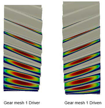
The lead crown values were kept to a minimum to increase effective face contact ratios while ensuring no edge loading, as revealed in the contact pattern studies conducted in the simulation software.
It became evident that Gear mesh 1, with its offset contact pattern, required lead slope correction. During the development of these lead corrections, it was discovered, through software simulations, that the necessity for lead correction could be reduced by flipping the helix hand due to the change in system deflections. After evaluating the impact on the calculated bearing life, the team opted to modify the helix hand in conjunction with the previously mentioned gear design enhancements.
As indicated in the literature review (Refs. 5, 6), it is understood that when designing for full load conditions, long tip reliefs offer superior PPTE reduction compared to short tip reliefs. Parametric simulation runs also demonstrated that longer tip reliefs yielded lower PPTE results, with the PPTE outcomes showing less sensitivity to lead and profile microgeometry tolerances. Consequently, the start of tip relief angles was reduced, alongside an increase in tip relief values, to minimize the PPTE. These start-of-tip-reliefs for each of the gear meshes were close to, but slightly less than the working pitch roll angle.
The simulation results of the macro and micro gear design improvements are presented in the “Verification” section.
Manufacturing Parameter Considerations and Virtual Analysis
The selection of the manufacturing process can also be influenced by the simulation results and limitations of traditional gear tooth finishing methods. Software simulations revealed that the tolerance of the start of tip relief had a significant impact on the PPTE values. Previous gear projects involving gears of similar size indicated that even with controlled heat treatment and an additional stress-relieving cycle, shaving could only achieve start-of-tip-relief roll angle tolerances of ±1.5 degrees. Simulation data indicated that this would lead to a notable increase in PPTE values. Further attempts to address this issue are discussed in the article “Lessons Learned from Earlier Trials” later in the paper. It became evident that gear shaving was not a viable solution to reduce these gear excitations. Gears that were originally manufactured under DIN 9 grade (using shaving) were upgraded to DIN 7 grade (using grinding) by opting for hard grinding as the finishing process. It is important to note that all gears underwent heat treatment for case carburizing throughout the trials mentioned in this paper.
From the first attempts at grinding the gear flanks, a sharp edge was visible at the transition between the involute and tip relief zones of the profiles. This sharp edge was a result of high tip relief amounts along with linear tip relief grinding method causing a sudden transition from pure involute. This sharp edge could have potentially caused its own excitation when in contact under load, creating noise. To mitigate this issue, smoother transitions were deemed necessary, requiring the implementation of parabolic tip relief and transition fillet radii instead of linear tip relief tooth grinding. Simulations also demonstrated superior PPTE values with parabolic tip reliefs compared to linear tip reliefs for each gear mesh.
It is acknowledged that, regardless of the fidelity of the virtual analysis model, it remains challenging to encompass all system and assembly-level parameters and behaviors in software simulations. In response to these unknowns, it was recommended that the tooth profile grinding manufacturer produce various min/max samples within the proposed microgeometry tolerance band. This approach would allow for the physical observation of noise improvements resulting from different values of profile slope (fhα), tip relief, and crown.
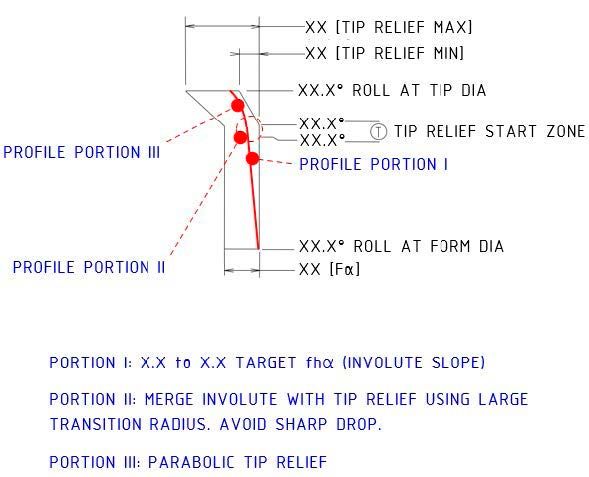
Figure 5A—Gear manufacturing profiles (Ref. 10).
Figure 5B—Special tip relief and transition instructions.
The three profiles above (Figure 5) referred to as Nominal, Minimum, and Maximum profiles illustrate the grinding trials described earlier. Utilizing a single flank grinding machine, various possible profiles were manufactured to simulate the effects of manufacturing variations in large batch production and to identify profiles yielding improved noise results. Lead charts were prepared alongside these profiles, where “Nominal,” “Min” and “Max” denoted the target, minimum, and maximum lead modifications based on the microgeometry of the proposed design. Special instructions for providing 2nd-degree parabolic tip relief and a smoother transition included specifying the intended profiles on the K chart such as Figure 5B.
Multiple samples of each design combination (nominal, minimum, and maximum) were produced for use in transmission applications during field and laboratory testing, marking a significant advancement in the solution’s development and testing phase. It was discovered that intentionally introducing a limited negative slope helped enhance noise levels, leading to the incorporation of these fhα modifications into the design.
Verification
Contact pattern validation is carried out to verify to check gears are manufactured based on desired gear profile and lead parameters. Physical contact patterns are also well aligned with the simulated gear contact pattern.
Figure 8—PPTE variation for new gear design.Figure 9—Baseline vs. new design response.
Transmission error, which is a major source for gear whine, showed significant improvement by accommodating gear macro and microgeometry improvements, listed below Figure 8.
PPTE throughout this research is depicted in the plots below. The blue markers represent PPTE at nominal design values while the black markers represent the minimum and maximum PPTE results of the tolerance study in the virtual simulation model.
With the proposed gear modification, field testing is executed to verify the response. By keeping the test methodology and instrumentation the same, noise data were recorded and analyzed. With the proposed modification, there was significant noise level reduction compared to the baseline design as shown in Figure 9. Also, jury testing was carried out for subjective evaluation to confirm the outcome, i.e., noise reduction. After confirming all these trials and meeting the noise reduction targets, the recommended design modification was implemented. This resulted in enhanced customer comfort.
Lessons Learned from Earlier Trials
Gear runout (Fr) was a key parameter of interest during the initial trials. It is commonly understood that gear runouts can sometimes lead to abnormal noise. Low runout gears, selected from production batches by inspecting each gear for runout, were tested in the application. While there was a considerable reduction in grinding noise and background noise of the gearbox, the identified gear mesh frequencies responsible for the noise issue showed no measurable or perceptible improvements in noise levels.
The initial design was manufactured using shaving as its finishing operation. The first attempt to reduce noise was made by opting for shaving instead of grinding as the gear-finishing process. This trial focused on gear microgeometry optimizations, with no macro geometry enhancements, manufactured by hobbing and finished by the shaving operation. However, inspections of the manufactured gears revealed limited control over microgeometry parameters such as the start of tip relief, shape of tip relief, fhα, and lead slope. Analysis of the measured gear flank topographies in the simulation model did not show any improvement in PPTE. This lack of improvement was confirmed during field application trials, underscoring that shaving, due to its inherent process characteristics, is not suitable as a finishing operation for gear noise sensitive to microgeometrical parameters.
Transitioning from shaving to grinding was aimed to enhance manufacturing accuracy, achieve better control over microgeometry parameters, and attain finer surface texture/roughness. While the shift from shaving to grinding improved the gear PPTE in simulation results, an unforeseen excitation emerged from the sudden drop in the involute profile at the transition from pure involute to the tip relief surface of the gear. This abrupt profile transition resulted in a visible edge on the ground gear flanks, leading to poor noise performance. It is crucial to study and smoothen this transition by incorporating a curved tip relief and a significant fillet radius at the start of the tip relief. This adjustment can be implemented in machine settings during single flank grinding or addressed in the design of a new dresser for the generative grinding process.
Gear flank surface finish was investigated separately as another parameter which could show improvement in gear noise. Upon trial minor subjective improvements were observed in noise, but there was no measurable data to support these noise improvement claims. It was concluded that for given application and design constraints, only surface finish was probably not a suitable solution to gear whine noise.
Conclusion
The literature review indicates a strong correlation between gear contact ratios and transmission error, as well as gear whine noise. The research findings are consistent with earlier work by Liu et al. (Ref. 1) which explains that a face contact ratio close to an integer is significantly associated with noise reduction.
As highlighted by Smith (Ref. 5), long tip reliefs offer greater benefits in full-load applications. Given that plowing represents a full-load scenario for the tractor under consideration, the study’s outcomes align with Smith’s insights.
The manufacturing trials lead to the conclusion that, for a specific gearing arrangement, negative profile slopes (fhα) exhibit superior noise characteristics compared to positive profile slopes. Intentional incorporation of such slopes in gear micro geometries can aid in reducing PPTE and potentially decreasing noise levels.
Furthermore, the study demonstrates the importance of achieving smoother transitions at the start of the tip relief, along with advocating for the adoption of parabolic tip reliefs over traditional linear tip reliefs.
Conducting contact pattern tests on a durability test bench proves instrumental in calibrating virtual simulation models effectively. It is crucial to accurately determine the torques transmitted through the transmission system, either through instrumentation or data acquisition during vehicle operation.
Acknowledgments
The authors would like to acknowledge the guidance and contribution of numerous colleagues at John Deere, without whom these efforts would not have been possible. Among these are Mr. Satish Wagh, Mr. Pravin Jadhav & Mr. Joy Fernandis from the drivetrain design group, Mr. Nilesh Patil, and Mr. Rahul Patil from the Virtual Verification group. We also would like to acknowledge the support of Mr. Pratap Jadhav & Mr. Amol Pimpale from the Physical Verification group. The authors are also very grateful for the solid support of management throughout the effort and their commitment of the necessary resources to successfully apply these technologies.
References
Liu, L., Ding, Y., Wu, L., & Liu, G. (2015). Effects of Contact Ratios on Mesh Stiffness of Helical Gears for Lower Noise Design.
Munro, R. G., & Houser, D. R. (1997, 2002). Transmission Error Concepts.
Lahoti, S., Patil, P., & Wagner, J. J. (2021). Gear Whine Noise Reduction by Transmission Error and Contact Pattern Optimization: Simulation and Testing Correlation. SAE Technical Paper 2021-01-1103. https://doi.org/10.4271/2021-01-1103.
J. Tuma., Transmission and Gearbox Noise and Vibration Prediction and Control, In: 16th International Congress on Sound and Vibration.
Smith J.D., Gear Noise and Vibration.
Niemann, G. and Baethge, J., “Transmission error, tooth stiffness and noise of parallel axis gears.” VDI-Z, Vol 2, 1970, No 4 and No 8.
Dr. R.J. White, Exploration of a Strategy for Reducing Gear Noise in Planetary Transmissions and Evaluation of Laser Vibrometry as a Means for Measuring Transmission Error.
ISO 6336-1:2019, Calculation of load capacity of spur and helical gears.
DIN 3961/3962/3963/3964/3967, Tolerances for Cylindrical Gear Teeth.
ISO 1328-1:2013, Cylindrical gears ISO system of flank tolerance classification.
GearLab at Ohio State University, Load Distribution Program.
K.R. Fyfe, E.D.S. Munck, “Analysis of Computed Order Tracking,” Mechanical Systems and Signal Processing, Vol. 11, pp. 187-205, January 1997.
First presented at the 2024 Fall Technical Meeting (FTM), October 7–9, 2024, Rosemont, IL. Printed with permission of the author(s). Statements presented in this paper are those of the author(s) and may not represent the position or opinion of the American Gear Manufacturers Association.