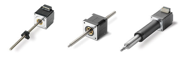
Telescoping style actuators are intended to perform more like the traditional rod-style actuators found in most industrial applications, while still having the benefits of a configurable stepper motor and lead screw-based unit. At its core, the telescoping actuator is a rotating screw configuration with extra housing components that “capture” the lead nut within a spline and use an internal bushing to provide some side and moment load support. Because these configurations incorporate guidance and support directly into their design, in many cases, they won’t need the external components that might otherwise be required. Other names for this style of actuator are motorized lead screw actuator, captive, electric rod and electric cylinder.
The mechanics of a telescoping SMLA are similar to those of a rotating screw configuration. The key difference is that its configuration integrates guidance and support components in the form of a splined cover tube and extension tube with a support bushing, which allows motion without the need for external components.
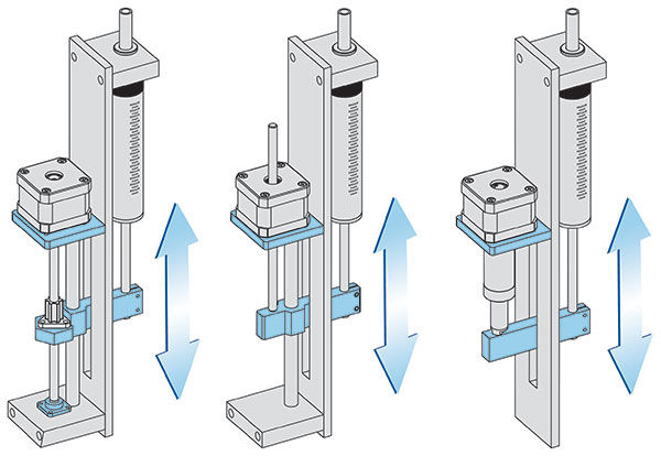
Figure 5: This fluid pump application example illustrates the typical mounting configurations for all three SMLAs (left to right: rotating screw, rotating nut, telescoping).
Installation
All three SMLA configurations have a similar installation process, which consists mainly of mounting the motor, supporting the lead screw if needed and attaching the load. The key differences lie in where the load attaches and how it is supported. (Figure 5)
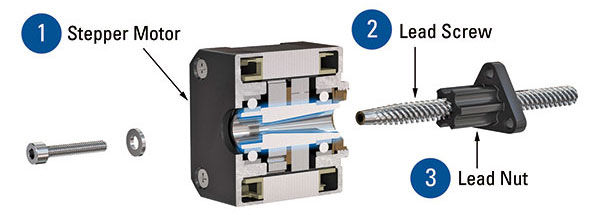
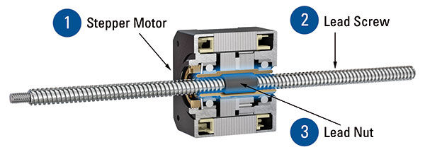
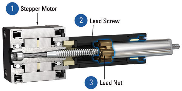
For rotating screw configurations, the load attaches to the lead nut, and the end of the lead screw will need to be supported with a bearing or bushing for longer lengths. For rotating nut configurations, the load is attached to the lead screw. And for the telescoping configuration, the load will be attached to the end-mounting on the extension tube.
Both rotating screw and nut configurations are meant to withstand axial loads only, so guidance and support in the form of linear bearings and guide rails will be required for proper function. Since guidance and support are typically integrated into telescoping actuators, the need for linear bearings and guide rails can be eliminated in many scenarios.
Sizing for Applications
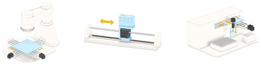
The SMLA’s high levels of customization and configurability lend it to countless application possibilities. Figure 6 shows a few common examples of SMLA applications.
Sizing an SMLA for a specific application then, mainly involves understanding the motor, lead screw and lead nut limitations. Each of these core components must be sized appropriately to ensure proper functionality and optimal life. Luckily, most manufacturers provide theoretical performance plots that consider these components, making it much easier to size an actuator quickly. These plots will usually take the form of a speed vs. load curve, and highlight the optimal performance range of the motor, screw and nut combination.
Figure 6: By reducing the total number of components needed, SMLAs are ideal for a wide variety of space-conscious applications, including (left to right): XY stage (rotating screws), horizontal positioning (rotating nut), and fluid pipetting (telescoping and rotating screw).
Julian Anton, design engineer at Thomson Industries, Inc., is responsible for new product design and development for lead screws and stepper motor linear actuators. He earned his Bachelor of Science in Mechanical Engineering from San José State University. Julian has been with Thomson for 7 years.
Dave Buckley, is an industrial automation manager at Motion Industries, with a focus on automation and linear. He has 55 years of experience in industrial design, specializing in fluid power before moving onto automation design in 1985. Initially spending 17 years in design engineering in the steel industry at Dofasco and Stelco (later US Steel), Buckley then moved to technical sales and became the Canadian Director of Marketing and Sales for the Bosch organization (then called Basic Technologies). He later moved on to be the Canadian Manager for THK America before landing at Motion Industries.
Comparing SMLAs
SMLAs enable a modular motion system design approach that allows engineers to achieve a solution that is highly tailored to their specific application requirements. Determining which of the three SMLAs is best depends on many application-driven factors.
Those seeking maximum customization or a truly unique combination of components should consider rotating screw actuators. Rotating screw designs are the most commonly deployed type of SMLA, so many engineers will already be quite familiar with them.
Applications that would benefit from a more compact, simpler actuator and that do not require an anti-backlash nut or many encoder options might be better served by rotating nut designs.
Engineers who prefer to drop in a more traditional, rod-style actuator design and whose applications would benefit from integrated guidance, support and built-in anti-rotation should consider the telescoping design. This configuration is also worth considering if reducing the overall component count is important because the integrated guidance/support components eliminate the need to purchase external ones. Table 1 summarizes the most common strengths and weaknesses of each SMLA configuration, as well as a few common application examples.
To help designers and integrators wade through the many options, SMLA manufacturers are increasingly offering online tools to help them quickly and easily configure solutions for their applications. For example, there are online selector tools that allow users to identify the right SMLA for their application in a matter of minutes, while immediately accessing performance characteristics, 3D models, pricing and lead time.
Applying automated selection tools in the context of an understanding of the design, mechanics, installation and sizing of the three main SMLA types can help guide motion designers and integrators to the optimal choice for their applications.
| Table 1: SMLA configuration comparison |
- Highly configurable
- Anti-backlash nuts available
- Easy-to-install encoders on the back of the motor
- Polytetrafluoroethylene (PTFE) coating of lead screw available
- Easy to maintain
|
- Lead nut more exposed to the elements
- Slightly more involved assembly process due to more mounting components
- The lead screw needs to be supported for longer lengths
|
- Pipetting
- Fluid Pumps
- XY Stages
- 3D Printing
- Life Sciences
- Rubber and Plastics
|
- Simple, compact design
- Simple mechanics
- Shortest overall length
- No visible rotation of components
|
- Rear protruding lead screw
- Less encoder options
- If available, less robust anti-backlash designs
|
- Fluid Pumps
- Horizontal Positioning
- Robotic Gripper
- Aerospace
|
- Integrated guidance and support
- Built-in anti-rotation
- Easy-to-install encoders on the back of the motor
- Usually has some level of environmental protection
- Simple mechanics
- No visible rotation of components
|
- Higher cost
- Stroke limitations
- Fewer customization options
- Longer collapsed length vs. the other configurations
|
- Pipetting
- Plate Vertical Positioning
- Monitor Tilting
|
For more information:
Visit MotionIndustries.com/PTE or find your linear solution here.