How to Select a DC Motor: Coreless and Iron Core Brushed DC Motors

How to Select a DC Motor: Coreless and Iron Core Brushed DC Motors
DC Motors
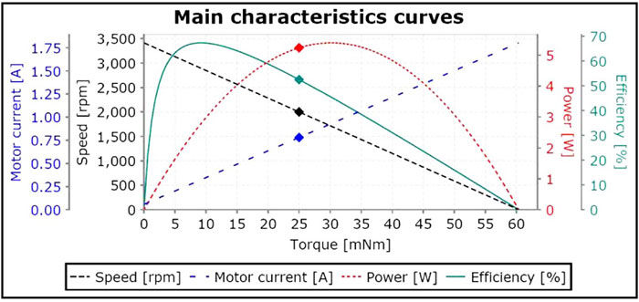
DC motors possess linear relationships that allow for very predictable operation. For instance, if enough voltage is applied across the terminals of a DC motor, the output shaft will spin at a rate proportional to that applied voltage. You can take the ratio of the applied voltage over the rated voltage and multiply that number by the no load speed and get the running speed. Also, if you decide to measure and plot the current and torque, you will have a simple straight line indicating yet another directly proportional relationship. When torque demands increase, so does the current. Plotting the torque and speed together, you will find that only two points of data are needed. Those are the no load speed and the stall torque. The entire motion control world, including manufacturers and designers, depend greatly on the premise that all these linear relationships will hold true. And they do because the laws of physics do not change! However despite their simplicity, selecting a DC motor for an application can still be a daunting task. There are many other variables that must be taken into account including dimensions, load, duty cycle, environment, feedback considerations, etc. Perhaps decoding some of the mysteries of motor operation will shed some light on the selection process.
Going for simplicity with brushed motors. If your application demands a reliable, time-tested, low cost motor, then brushed DC motor technology may be what you're looking for. The key here is simplicity. A brushed motor is designed to run off of straight-line DC voltage and can even be connected directly to a properly sized battery. When a DC voltage is applied across the terminals of a brushed motor, a potential difference is achieved and current is induced into the windings on the rotor. The brushes allow this current to flow through a rotating mechanical switch called a commutator. The rotor windings act as electromagnets and while powered form 2 poles that terminate at the commutator segments. This entire assembly is known as an armature. While rotating the commutator allows the direction of the current to reverse two times per cycle. This permits the current to flow through the armature and the poles of the electromagnets attracting and repelling the permanent magnets that encompass the motor's inner housing. As the energized windings of the armature pass the permanent magnets, the polarity of the energized windings reverses at the commutator. This process is called mechanical commutation and only found in brushed motors. During the instant of switching polarity, inertia keeps the rotor going in the proper direction and allows the motor to continue turning. The result is power in its mechanical form measured in watts. Mechanical power is the product of torque multiplied by the rotational distance per unit time (or speed). Torque is the force vector component that rotates a load about an axis and is inversely proportional to speed (Eq. 1):
PMechanical = Mω (1)
Where,
P = Mechanical Power; M = Torque; ω = angular velocity
From the equation above, we see there is a price to pay for how much power a motor can deliver. The amount of current that flows through the windings, directly affects to the torque the motor can produce. Adjusting the supply voltage will force a proportional change in the motor's speed so the output shaft's angular velocity (speed) will have to be sacrificed as torque demands increase. There are also other factors that come into play such as losses. For example, static friction is defined as the friction torque a motor must overcome in order for the shaft to begin turning. Then there are brush contact losses caused by the friction of the brushes upon the commutator. Also, copper losses in the form of heat sometimes referred to as I2R losses play a role. Electrical power is represented in Eq. 2.