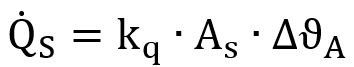
Let’s start by solving the total dissipated heat flow Q ̇:
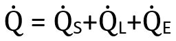
Where:
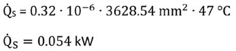
In this case, the heat emitting bearing seating area, AS, is the same as Ar used in ISO 15312. Again using our 6205 example:

ΔϑA is the difference between operating temperature and ambient temperature. For ease of comparison, we will use the operating condition defined in ISO 15312 as 70°C. If we are operating at room temperature, ΔϑA = 47°C (23°C to 70°C).
Schaeffler provides the chart for the kq value. Below, the 1 line is for axial bearings and 2 is for radial bearings which includes the 6205 ball bearing. This gives us about 0.32 x 10⁻⁶. Our description states we should have a value between 0.2 – 1.0 x 10⁻⁶ which seems reasonable. There are a lot of unspecified factors here depending on architecture which is characterized by the large gray area. The faster the system can self-cool, the larger this value is.
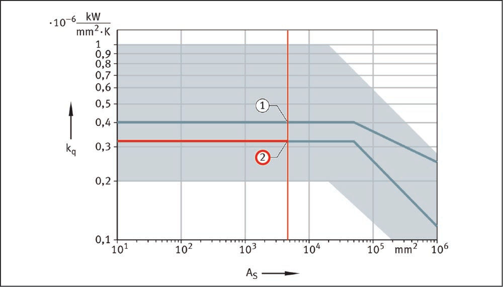
Figure 2— https://medias.schaeffler.us/en/speeds
Therefore:
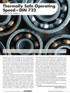
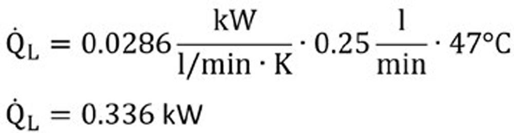
Now on to heat flow dissipated by the lubricant.

V ̇L is simply the oil flow. These numbers are always somewhat of a guess if you have a passive oil system. In these cases, you can just pick a reasonable middle of the road value ~ 0.25 l/min. There are published formulas that will give you estimates on needed oil flow rates based on speed, load and temperature.
Now we have;
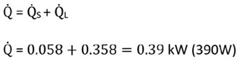
Now we can solve the total dissipated flow rate. For this exercise, we will just set the external heating / cooling factor Q ̇E to zero. If you have a heater or cooler, you will add that value here.
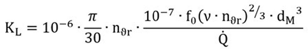
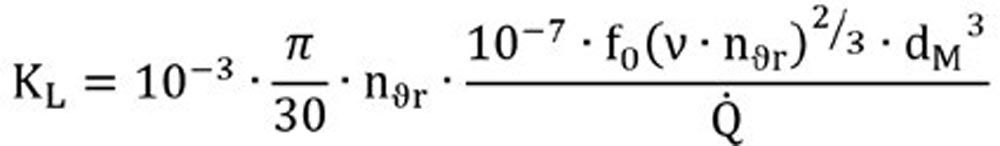
Now we move to the lubricant factor:
The bearing factor f0 is a table value that can be found in ISO 15312 and DIN 732 and referenced in public literature. In our case, the 6205 ball bearing has f0 = 2.0 (for oil bath or recirculation).
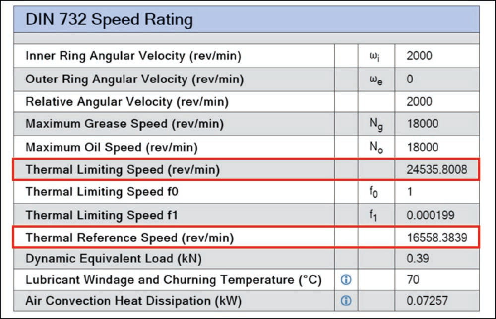
ν is the kinematic viscosity at operating temperature. For continuity, we will keep the value of 12 mm2/s as defined in ISO 15312. Recall that we defined our operating temperature at 73°C. Regardless of where you set your operating temperature, just make sure it is consistent. Again, we revisit our ISO 15312 results for the thermal speed rating nϑr: 13,300 rpm. dm is the mean bearing diameter (6205): (52+25)/2 = 38.5 mm
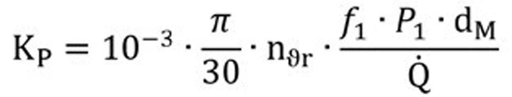
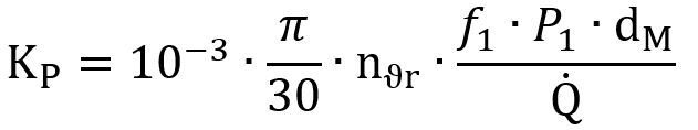
Now on to the load factor KP.
Most of these variables have now been defined—we just have f1, the other bearing factor and P1, the decisive load. f1 is as a simple formula in DIN 732: 0.0009∙(P0⁄C0)0.5 P0 is the applied equivalent static load and C0 is the static load rating. If axial loads are light, P0 can be estimated as the applied radial load. For the 6205 C0, we will use the SKF rating of 7.8kN. For P1 we will continue using the ISO 15312 parameter for ease of comparison – which was 5% of Cor (7.8kN) or 390N. Now we have f1=0.0009(0.39⁄7.8)0.5=0.0002.
Now we can solve KP.
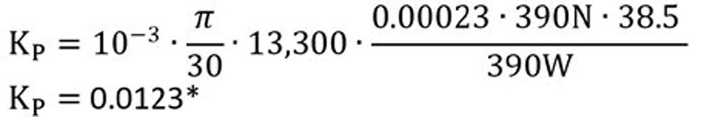
It is coincidental that P1 and Q ̇ are the same value. Units are included for clarity.
*Schaeffler also provides a chart for basic configuration for reference. We can see here that for light load, the KP factor can easily run off the chart > 1. If we use the ISO 15312 value of 390N, this would give us a Co/P (7.9/.39) of 20. Something doesn’t seem to be lining up between the chart and the formula—the formula result seems too low. We will use our software to skip the guessing game, but for meantime, let’s use the old college trick of setting the variable to 1 as a placeholder.
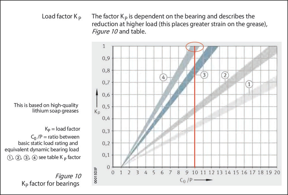
Figure 3—https://www.schaeffler.com/remotemedien/media/_shared_media/08_media_library/01_publications/schaeffler_2/catalogue_1/downloads_6/gl1_de_en.pdf
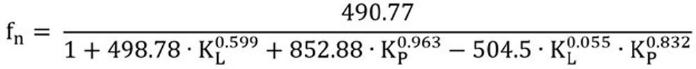
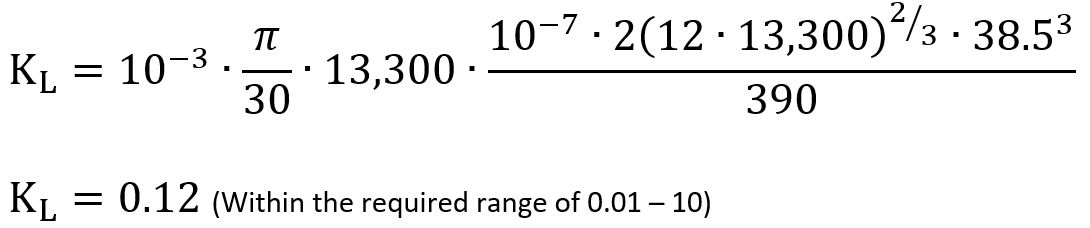
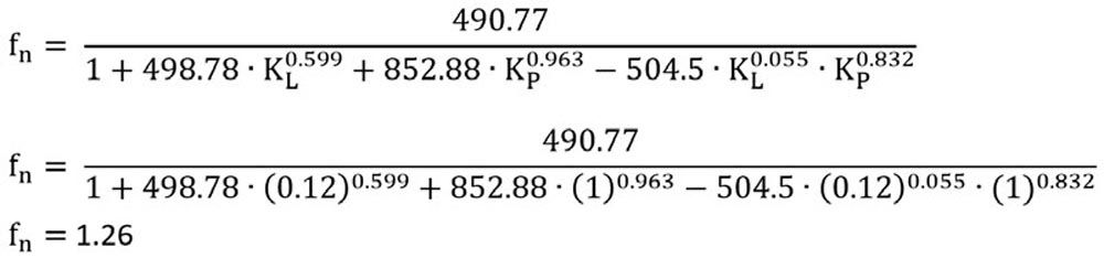
Let us try solving fn with KL: 0.12 and Kp: 1.
This answer doesn’t seem terrible. We can do a little reverse engineering in Masta to see if our Kp assumption holds any water. Using all of the same operating assumptions from ISO 15312:
fn = 24,535/16,558 = 1.48
Working Schaeffler’s fn chart backwards, we see that the Kp value should have been around 0.69. I don’t have a quick answer on how to get that number from the formula. This may need some clarification with our ISO folks.
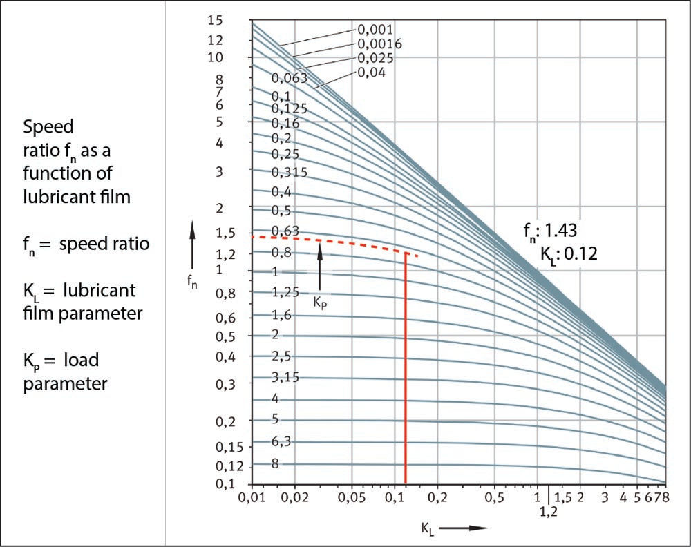
Figure 4—https://medias.schaeffler.us/en/speeds
We can solve that problem another day. Now let’s solve our thermally safe operating speed with the software derived speed ratio:
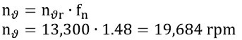
Alright, this is looking more promising. According to this standard, under the given conditions, we should be able to run this 6205 at 19,684 rpm continuously without overheating. Continuously is an important note because this means we can likely overshoot this value for brief periods. Of course we must always be cognizant of the mechanical limitations of the cage.
I thought it would be fun to compare some supplier’s website results and Masta to see if our calculations come close. Many suppliers do not include thermal ratings—these are some of the few that do.
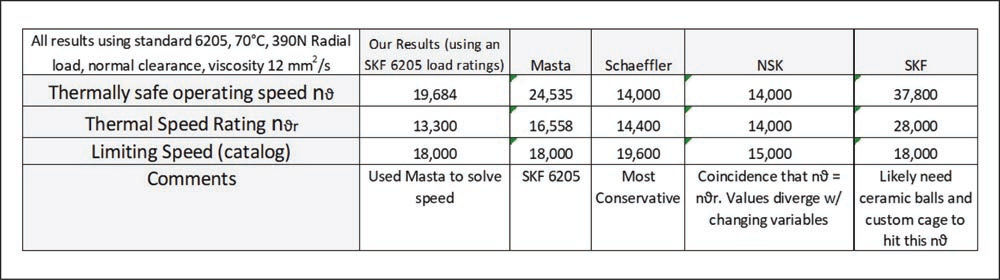
I am pretty satisfied with these results. Our hand calculated numbers are not as aggressive as Masta, but higher than the limiting speed—just what I would expect. Schaeffler and NSK are on the conservative side, but I strongly suspect you would receive better numbers with an application review. You should consult your SKF representative about their numbers.

Nomenclature
nϑ—Thermally safe operating speed RPM.
nϑr—Thermal speed rating.
fn—Speed ratio.
NR—Frictional power kW.
Q ̇—Total dissipated heat flow W.
MR—Total frictional torque Nmm.
f0—Bearing factor for frictional torque as a function of speed.
ν—Kinematic viscosity of the lubricant at operating temperature mm2/s.
f1—Bearing factor for frictional torque as a function of load.
P1—Decisive load: radial load for radial bearings, axial load for axial bearings N.
Q ̇S—Heat flow dissipated via the bearing seating surfaces kW.
Q ̇L—Heat flow dissipated by the lubricant kW.
Q ̇E—Heat flow. For heating by external source (+), for cooling by external source (–).
KL—Lubricant parameter.
KP—Load parameter.
Kq—Heat transfer coefficient 10–6 kW/(mm2 · K) Heat transfer coefficient, as a function of the bearing seating surface. This is dependent on the housing design and size, the housing material and the installation position. For normal installation, the heat transfer coefficient for bearing seating surfaces up to 25,000 mm2 is between 0.2·10-6 kW/(mm2 · K) and 1.0·10-6 kW/(mm2 · K).
AS—Heat-dissipating bearing seating surface mm2.
ΔϑA—Difference between mean bearing temperature and ambient temperature K.
V ̇L—Oil flow l/min.
ΔϑL—Difference between oil inlet temperature and oil outlet temperature K.
B—Bearing width mm.
d—Bearing bore diameter mm.
dM—Mean bearing diameter (D + d)/2 mm.
D—Bearing outside diameter mm.
d1—Outside diameter of shaft locating washer mm.
D1—Inside diameter of housing locating washer mm.
T—Total width of tapered roller bearing mm.