Induced Axial Load
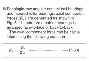
Every bearing that has a non-zero contact angle will generate an axial load as a radial load is applied. This generated load is referred to by a few different names, i.e. — generated axial force, calculated thrust load, or as I first learned it — induced axial load (IAL). The concept is fairly simple; in contact ball bearings or tapered roller bearings, the ball or roller is sitting at an angle. When you add a radial load, you are trying to push the roller down the hill. This generates an axial component that can be substantial.
Usually tucked in an obscure corner of the bearing catalog there will be a vague reference to the IAL with a loose description of how to calculate it and some form of an application description that nobody understands.
Figure 1: Koyo ball & roller bearings p. A38 - B2001E-6.
The basic formula is very simple, though some applications can have non-obvious aspects, which we will cover (Eq. 1).
Where Fac is the IAL, Fr is the applied load and Y1 is the dynamic axial load factor, which is usually found in the catalog line item for the specific bearing. Y1 is just a calculated factor for the convenience of not having to go through the statics of the contact angles of the bearing to calculate the IAC. The bearing companies have done that work for us.
Figure 2: NSK rolling bearings p. B123 - E1102k.
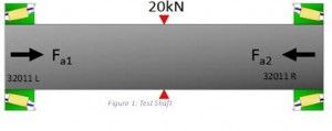
Let’s have a look at a simple example; we will take a 250 mm shaft and put a pair of face-to-face 32011’s on each end and apply a 20 kN load directly on the center of the shaft.
Figure 3: Test shaft.
Now looking at the results in Figure 4, we see the radial load split between the 2 bearings as we would expect with an additional axial load that we did not apply. This is your IAL.
Figure 4: Test shaft loading results.
Let’s see how this compares with our formula (Eq. 2):
That is an easy and obvious result for this example. What isn’t as obvious is that in equally sized and loaded bearing arrangements, this will not affect the dynamic equivalent load P = XFr+YFa, which is what you use to calculate fatigue. See Figure 5 and you see that the equivalent load is still in fact only 10 kN.
Figure 5: Test shaft dynamic equivalent load.
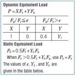
The reason for this is baked into the formula for the dynamic equivalent load. For this purpose, I like the NSK Rolling Bearing catalog E1102 because they put the equivalent load formula on every single page that contains a non-zero contact angle bearing, always reminding us of the importance.
Figure 6: NSK rolling bearings — single row tapered roller bearing section.
For the 32011 XJ series (15⁰ contact angle), from Figure 2, the Load Ratio e is 0.41. The dynamic equivalent load changes when the ratio of radial to axial load exceeds the load ratio value. In our case, Fa/Fr = 3.31/10 = .331, which is below the e value of 0.41. This places us in the left box shown in Figure 6; you can see that on that side that the axial load factor Y is 0 and the radial load factor is 1, which means you can neglect the induced axial load in the fatigue calculation.
So — this long-winded explanation to tell us that we can ignore IAL? Thanks, Norm. Haang on now — I’m going somewhere with this. Let’s see what happens when we move the load off center, like many gear systems.
Figure 7: Test shaft—offset load.
As you may have run into, when we are balancing non-symmetrical loads on angular contacts or tapers, we need to consider that the effective load center is at the apex of the contact angle of the cups. Fortunately, this is another tabulated value that can also be found in Figure 2, denoted as a. For the 32011 XJ, this value is 19.7mm.
To balance these loads, you can use simple proportion techniques for the radial loads:
Load on 32011L (Eq. 3):
Load on 32011R (Eq. 4):
Now calculate the IAL on the larger value to start with (Eq. 5):
Now calculate the axial load on the lighter loaded bearing. Hang on a second — these are connected through a solid shaft. Remember that whole action-reaction deal that one guy used to talk about? We can’t really have two different axial loads on the same shaft, can we? The IAL of the heavier loaded bearing is the IAL of the shaft. Let’s compare with our software results:
Figure 8: Test shaft offset load results.
Just for kicks, let’s take a second look at Figure 4 and see what our load ratios are. Recall that our load ratio e is 0.4 for this bearing, and if our Fa/Fr ratio exceeds e, then we need to use a different calculation.
For 32011L Fa/Fr = 4.9/14.7 = 0.33. Since 0.33 ≤ 0.4, we can neglect axial loading for the dynamic equivalent load. I always remember what my first wiry haired physics professor Dr. Lupton beat into my head; loads never, ever, ever, eeeever cancel. They can balance; they don’t cancel. This is especially important to remember in IAL situations. The axial load compressing or tensioning the shaft is still very much real and present even though they may balance.
Figure 9: NSK Rolling Bearings — single row tapered roller bearing section.
For 32011R Fa/Fr = 4.9/5.26 = 0.93. Since 0.93 ≥ 0.4, we need to consider axial loading and need to use the other formula. This is an interesting development. Now we are using two different formulas for the same bearing number on the same shaft due to IAL. Let’s see if this affects our results (Eq. 6):
P = XFr + YFa = 0.4(5.26) N + 1.5(4.9) = 9.45 kN
If we swap our exact values over to match the software just to remove differences to rounding errors (catalogs usually round in the conservative direction) (Eq. 7):
P = XFr + YFa = 0.4(5.23) N + 1.46(4.63) = 8.85 kN
And comparing these values with our software results (Fig. 10):
Figure 10: Comparison of values shown above with software results.
Well, this is certainly interesting. If we had neglected the differences in load ratios, we may have calculated the load on 32011R as 5.26 kN instead of 8.85 kN. This isn’t just underestimating the loading by (1-5.26/8.85) = 40%; this is overestimating the bearing life by (8.85/5.67)10/3 = 5.6 times! The good news is, if you are dealing with a system like this with the same bearings, the heavier-loaded bearing is still going to be much heavier loaded, and you will never know that you incorrectly calculated the load on the lighter bearing. However, if you are trying to reduce the size of the lighter loaded bearing and neglect IAL, you could be in for an unfortunate surprise.


