Welcome Back!
Last week in our bearing shaft and housing fit discussion, we covered the IT chart — along with the shaft and housing charts — just to understand the terminology going forward.
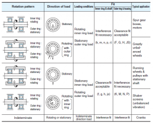
Figure 1 provides a very broad overview of how bearings are often sized to shafts and housings in order to avoid excessive spinning, galling, fretting, walking, etc. You may notice that the top box covers a good portion of our applications. As a rule-of-thumb, if you have a spinning shaft with a stationary housing, and a load that is transmitted through the shaft, you should try to press fit on the shaft and slip fit on the housing. In the less common scenario where the load rotates with an outer ring — such as intentionally vibrating machines like shaker screens and vibratory rollers — you will swap the fits; a press fit on the housing and slip fit on the shaft. All we are doing here is pressing on the surface that is most likely to slip. In outer ring rotating applications, such as wheel bearings and crane sheaves, the housing will have a press fit and the shaft will have a slip fit.
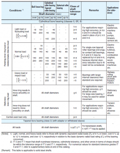
Similar to Figure 1, (Fig. 2, left) breaks the applications up into two parts — inner ring rotation and outer ring rotation. For inner ring rotation, we further segregate into the magnitude of loads. Some people are surprised when first reviewing this chart that a “heavy load” for a bearing is defined as something above 12% of the dynamic load rating. Most bearing companies follow suit with this guideline. This is specifically talking about sustained loads. We certainly have plenty of applications that can push the bearings to 100% of the dynamic rating or more, but those are excursions, not sustained loads. Under normal operating conditions, we usually are somewhere below 10% of the dynamic rating. Also important to note with this chart are its “normal” classes of bearings; i.e. — class 0, normal, and the slightly modified 6 or 6x (the vast majority of your bearings will
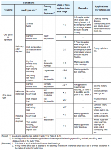
Of course, we’ve included a corresponding housing chart as well (Fig. 3). Again using our previous bearing with the 100 mm outer diameter, and assuming we have a one-piece housing with the normal stationary loads, the chart recommends an H8. This would be a fairly typical arrangement for a pair of ball bearings supporting a rotating shaft.
This is all good information, yet it fails to address all of our scenarios. There are many applications that, due to manufacturing or
We will discuss some options for handling these hurdles next week.


