Fitting the Inner Ring to the Shaft
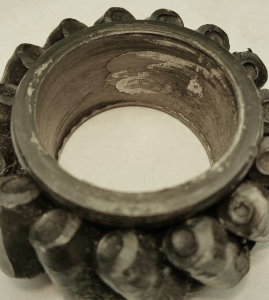
I don’t recall a time during the startup of a new program where an engineer unfamiliar with heavy load  axle testing didn’t want to completely stop a bearing from turning on a shaft. The logic is reasonable; if a hard pressed metal on metal surface is slipping, there is going to be material movement. If there is true turning on the bearing on a shaft, that can certainly be true and must be corrected by tightening up the fit, but most of the time, the indications of movement is just a creeping movement driven by the mechanics of the load. If we have a good press fit, something above 100 MPa of hoop stress, it doesn’t take long to realize that the bearing cannot transmit enough torque through the rollers to turn the cone. As one side of the bearing cone is loaded, the material slightly expands elastically while the opposite side is loosening up. As the cone progresses through the load zone, this acts somewhat like having a wave in a carpet. You can move a large carpet across a floor by pushing small waves along the direction you want to move, rather than move the whole carpet at the same time. If there is no material movement on your shaft following a hard test, but you see indications of turning; you are not “spinning” on the shaft. This is just the bearing lightly creeping around the shaft and is often harmless. Sometimes trying to tighten the fit hard enough to stop it will do more harm than good.
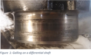
Now, let’s not confuse this with true spinning or turning. Figure 1 shows a condition that needs to be
 corrected because the shaft is galling and this will result in a wear surface. This problem will eventually start to generate heat as the fit continues grinding material away and will likely shorten the life of your system.
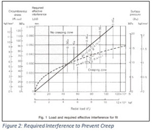
Figure 2 shows a simple chart showing the effective fit required to prevent creep. It would be great if we could simply follow the line up to point we need and call it good.
 Unfortunately, we have tolerances to deal with that drive the limits. Often, the best we can do is hold perhaps a 0.05mm range in fit. This range covers half of the chart. In this case, we target a low end fit range and then determine if the upper end resides within allowable hoop stress. Most bearing companies will recommend a max. hoop stress of 120 MPa for through hardened bearings and 180 MPa for case carburized.
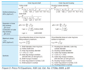
The max. hoop stress calculation can be found in most bearing handbooks. Figure 3 is one version from NSK’s Technical Report. Many companies will come up with a generic rule of thumb for bearing fits to save the time of going through this exercise every time. I prefer to spend some time up front to set up a good spreadsheet calculator and the dial in each application for its unique characteristics.
If you don’t have NSK’s Technical Report, download it here for free: http://www.jp.nsk.com/app01/en/ctrg/index.cgi?rm=pdfView&pno=e728g


