Almost daily I’m asked about the switched reluctance motor (SRM) — a motor that was invented more than 100 years ago. But only in the 1980s did it come back into focus, due to the work of Dr. Peter Lawrence, and especially Prof. Tim Miller.
The appeal of the SRM is in the fact that it does not use any permanent magnets, aluminum-cast or wound rotors. Figure 1 shows a basic, 3-phase SRM, and in Figure 2 we show the torque/current profile.
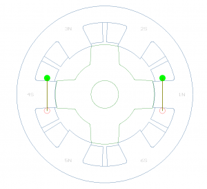
This motor consists of 6 stator coils, each of which is wound around a single tooth, with each two opposing coils forming a motor phase. The rotor is generally constructed from stamped laminations, but sometimes it can be made from a solid magnetic metal. This in theory is a very appealing, low-cost construction.
The SRM did enjoy some very visible success in the marketplace; e.g. — the Neptune washer used an SRM drive system made by Emerson, and the company also introduced a line of industrial variable-speed SRMs.
Despite these success stories, SRMs are not very widely available, and those that are in production are generally highly customized motors. There are several reasons for this. First, SRM construction was not as low-cost as its promoters often claimed. The SRM required a very small airgap, which in turn increased the cost of the mechanical construction; and, the SRM typically requires thinner laminations compared to AC and brushless PM, which can add a lot of expense to the motor.
The early SRMs had a torque profile with large torque variation vs. angular displacement that resulted in torque pulsations and noise.
Control of the SRM is also more complex than that of a brushless motor, and the required sensor accuracy often precludes use of low-cost Hall sensors to achieve best performance. The SMR drive does not use the standard H-bridge topology that brush, brushless and AC induction motors use. As a result — unlike in the AC and brushless inverter market — few integrated power components were available for SRM drives and the drives are generally more expensive compared to brushless and AC inverters.
And last, many of the early SRM implementations were fairly noisy and the SRM was quickly associated with excessive acoustic noise — even though the Emerson washer design and other SRMs were in fact very quiet and comparable in noise levels to PM brushless.
Despite all of the above, today customers continue looking at SRM solutions for their application needs. As magnet prices increase and the supply may be uncertain, the SRM offers a stable and predictable, long-term cost forecast. Modern SRMs also have changed from the original designs, as SRMs can now be designed that operate efficiently and quietly, with low-torque ripple and using larger airgaps. We have designed smaller SRMs with up to 3 mm airgaps, and the most recent designs feature tooth tips similar to those found on AC and brushless stators for improved efficiency and lower torque ripple.
Even though today’s standard SRM will be more efficient than an AC induction motor, the SRM is still limited to certain niche markets.
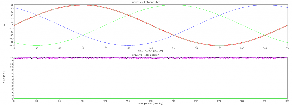
But recent developments in the SRM’s close cousin — the synchronous reluctance motor (SYR) — may fill the need for lower-cost motors (without permanent magnets, aluminum-cast or wound rotors). Figure 3 displays a typical SYR motor layout; Figure 4 provides its current and torque profile.
The stator is identical to that of a brushless or AC motor; the rotor is laminated with stamped slots. (Note: There is another construction available that won’t be considered here, as it has little practical value, in my view.) This motor can be powered by a standard AC inverter topology and, in some cases, can even use the same software if the parameters are adjusted properly. Similar to the brushless motor and the SRM, there are topologies where the winding will span a single tooth that potentially allows for the coils to be bobbin-wound.
In Figure 5 we see a small SYR that was developed for a battery-powered tool application, and that was operated from a brushless motor drive with minor software modifications.
SYRs also tend to run quieter than the SRM and are better suited to operate efficiently with larger airgaps. We have studied the SYR in high-speed applications where they perform better than both SRM and PM designs. The SYR appears to incorporate all the benefits of a reluctance motor, i.e. — stable cost with no magnets — with the benefits of using standard volume inverters.
ABB has successfully introduced a line of SYR variable speed motors for industrial applications. The SYR appears to incorporate all the benefits of a reluctance motor, namely stable cost with no magnets, with the benefits of using standard volume inverters. Therefore the designer should consider the SYR for new design projects.
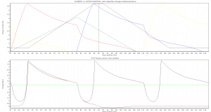
The appeal of the SRM is in the fact that it does not use any permanent magnets, aluminum-cast or wound rotors. Figure 1 shows a basic, 3-phase SRM, and in Figure 2 we show the torque/current profile.
This motor consists of 6 stator coils, each of which is wound around a single tooth, with each two opposing coils forming a motor phase. The rotor is generally constructed from stamped laminations, but sometimes it can be made from a solid magnetic metal. This in theory is a very appealing, low-cost construction.
The SRM did enjoy some very visible success in the marketplace; e.g. — the Neptune washer used an SRM drive system made by Emerson, and the company also introduced a line of industrial variable-speed SRMs.
Despite these success stories, SRMs are not very widely available, and those that are in production are generally highly customized motors. There are several reasons for this. First, SRM construction was not as low-cost as its promoters often claimed. The SRM required a very small airgap, which in turn increased the cost of the mechanical construction; and, the SRM typically requires thinner laminations compared to AC and brushless PM, which can add a lot of expense to the motor.
The early SRMs had a torque profile with large torque variation vs. angular displacement that resulted in torque pulsations and noise.
Control of the SRM is also more complex than that of a brushless motor, and the required sensor accuracy often precludes use of low-cost Hall sensors to achieve best performance. The SMR drive does not use the standard H-bridge topology that brush, brushless and AC induction motors use. As a result — unlike in the AC and brushless inverter market — few integrated power components were available for SRM drives and the drives are generally more expensive compared to brushless and AC inverters.
And last, many of the early SRM implementations were fairly noisy and the SRM was quickly associated with excessive acoustic noise — even though the Emerson washer design and other SRMs were in fact very quiet and comparable in noise levels to PM brushless.
Despite all of the above, today customers continue looking at SRM solutions for their application needs. As magnet prices increase and the supply may be uncertain, the SRM offers a stable and predictable, long-term cost forecast. Modern SRMs also have changed from the original designs, as SRMs can now be designed that operate efficiently and quietly, with low-torque ripple and using larger airgaps. We have designed smaller SRMs with up to 3 mm airgaps, and the most recent designs feature tooth tips similar to those found on AC and brushless stators for improved efficiency and lower torque ripple.
Even though today’s standard SRM will be more efficient than an AC induction motor, the SRM is still limited to certain niche markets.
But recent developments in the SRM’s close cousin — the synchronous reluctance motor (SYR) — may fill the need for lower-cost motors (without permanent magnets, aluminum-cast or wound rotors). Figure 3 displays a typical SYR motor layout; Figure 4 provides its current and torque profile.
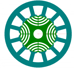
The stator is identical to that of a brushless or AC motor; the rotor is laminated with stamped slots. (Note: There is another construction available that won’t be considered here, as it has little practical value, in my view.) This motor can be powered by a standard AC inverter topology and, in some cases, can even use the same software if the parameters are adjusted properly. Similar to the brushless motor and the SRM, there are topologies where the winding will span a single tooth that potentially allows for the coils to be bobbin-wound.
In Figure 5 we see a small SYR that was developed for a battery-powered tool application, and that was operated from a brushless motor drive with minor software modifications.
SYRs also tend to run quieter than the SRM and are better suited to operate efficiently with larger airgaps. We have studied the SYR in high-speed applications where they perform better than both SRM and PM designs. The SYR appears to incorporate all the benefits of a reluctance motor, i.e. — stable cost with no magnets — with the benefits of using standard volume inverters.
ABB has successfully introduced a line of SYR variable speed motors for industrial applications. The SYR appears to incorporate all the benefits of a reluctance motor, namely stable cost with no magnets, with the benefits of using standard volume inverters. Therefore the designer should consider the SYR for new design projects.