Ball Bearing Fitting Series: Basics of Fit Charts
I recently finished a decent-sized project where I had to define several ball bearing fits for a prototype — all with different fitting arrangements. I have done this so many times, I normally don’t think much about it. But this time I was training a young engineer and kind of had a new-found respect for the number of steps that go into getting that “perfect fit” the first time. Now, don’t get me wrong; when the new parts arrive for the first prototype build, I’m pacing outside the lab doors, wringing my hands — just like everyone else. It usually turns out ok. In this series, we will start by understanding the basic fit charts, then move into understanding the application, then on to calculating residual clearance after mounting, and finally, determine shaft and housing dimensions.
Let’s begin with the shaft and housing fit chart that you can find in most bearing catalogs. An image search of “shaft and housing fit charts” will also pull up a few dozen versions for you as well. I like this one from Koyo because it shows the tolerance lines (single plane mean () diameter deviation) and clearly defines the clearance, transition and interference fit zones. The bottom half of the chart is the shaft fit section and the top half is the housing fits. Notice the shaft fit letters are in lower case in contrast to the upper case letters in the housing section. The vertical location of the blocks is meant to represent the position of the bearing relative to the shaft. Notice on the left, the f6 fit is a very loose fit, so the block is dropped away from the lowest tolerance line. This indicates that an f6 shaft would never interfere with the bearing. In contrast, the p6 fit on the other end would always be in interference with the shaft. The vertical size of the block is meant to represent the size of the tolerance range which is proportional to the standard international tolerance grade (IT). Notice the 5 and 6 blocks are very short, while the 7 blocks are long. The 5 and 6 blocks are very tight precision, while the 7 blocks have a larger tolerance. The same rules apply to the housing side in that things are just represented a little differently because a clearance housing is larger than the bearing outer diameter, while a clearance shaft is smaller than the bearing inner diameter. To summarize this chart, we start with the fit letter designation (lower is looser), followed by the IT grade (larger number = larger tolerance).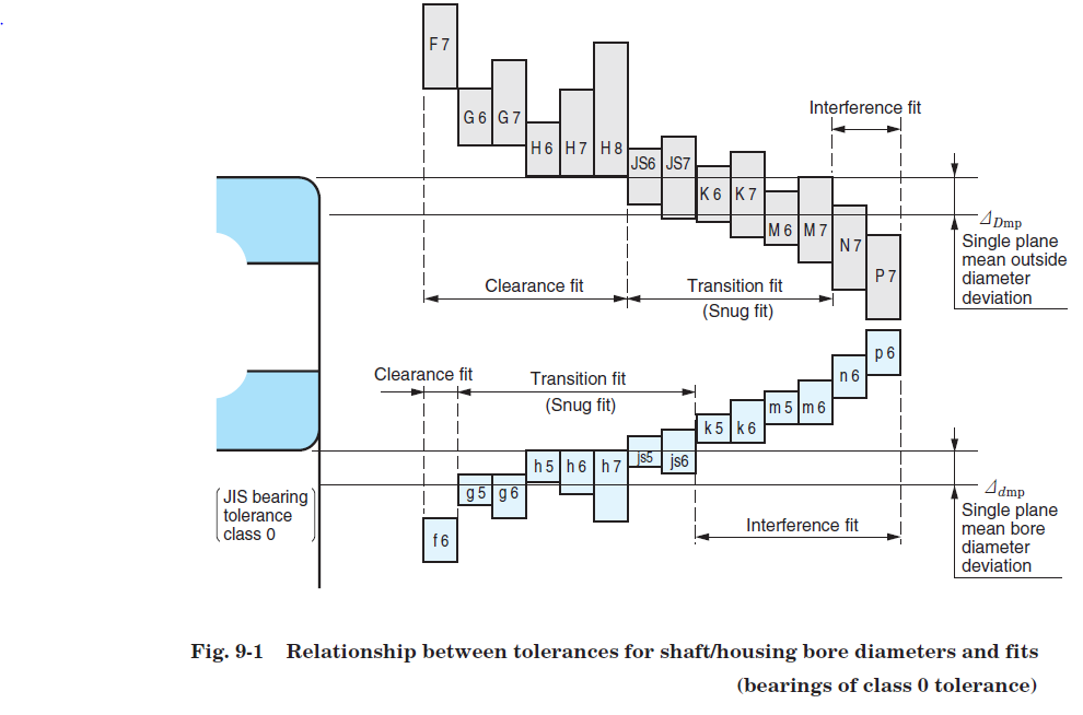
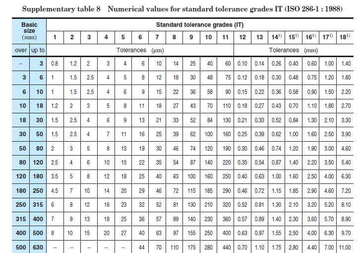
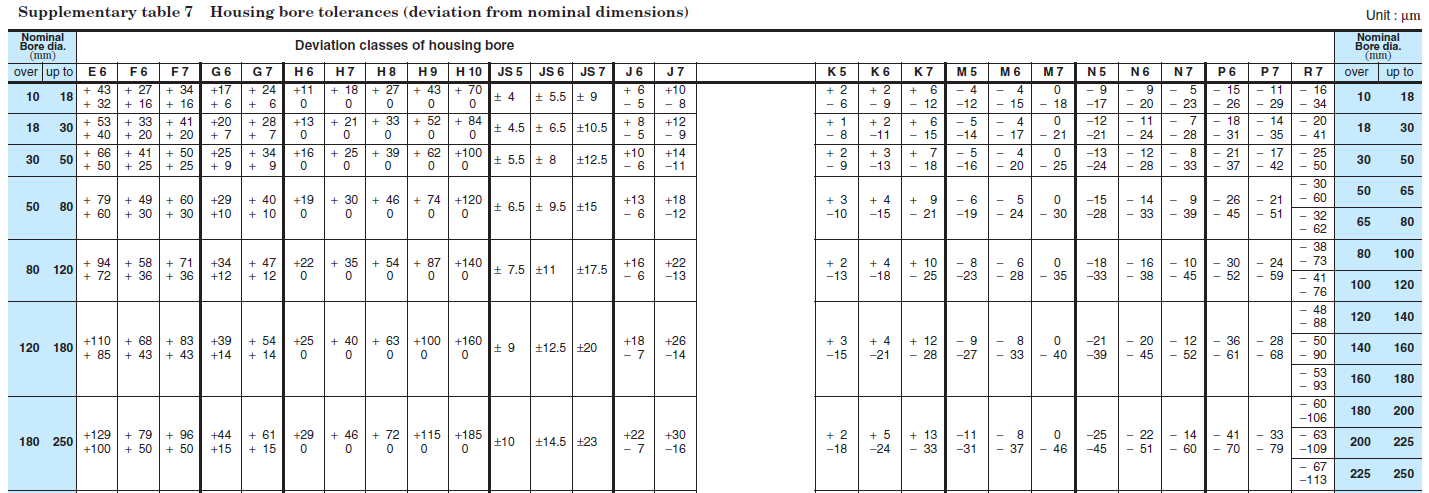
What you are going to do here is take your mean housing dimension and add those dimensions to it. For a 100 mm housing with an E6 tolerance, your housing is going to be 100.072 – 100.094. If your housing department tells you to take a hike, they are holding 50 µm, just jump back to your IT chart, look across the 100 mm line until you see something close to 50 µm. In this case, that is an IT8. So from Table 3 you need a column that ends in 8. Of course these don’t have to be an exact match; we are eventually going to deviate. Just to get started, it looks like an H8 might be a good match.