Method B makes it possible to estimate the additional dynamic loads without complex and expensive measurements and simulations. For this purpose, the gear stage is converted into a single-mass oscillator to enable classification with respect to the speed. A distinction is made between the four ranges shown in Figure 2. In the subcritical range, depending on the gear set, preresonances with corresponding local maxima can occur with regard to the additional loads. Method B assumes an additional load that increases linearly with the speed and approximates the actual additional loads. In the area of the main resonance, the additional load becomes maximum and is represented by a constant value. The transition region is characterized by a linear decrease of the additional load. In the supercritical region, the additional load is constant. The amounts of additional load are calculated separately for each range, taking into account the gear geometry (e.g., rotational inertia, meshing stiffness). Method C is based on method B and uses further simplifications (Ref. 22).
The described model approach of method B is often not sufficient, since the vibrations excite the entire drivetrain and thus influence the vibration amplitude and frequency. The course of the actual torque variation is approximated by a linear course of the KV factor in the calculation according to ISO 6336. Drivetrain-dependent resonance points in the sub- and supercritical range are not taken into account. This can lead to critical resonance points not taken into account, especially in the case of multistage gearboxes and complex drivetrains (Ref. 22).
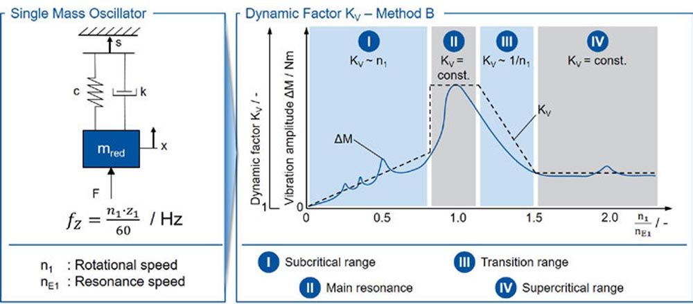
Figure 2 Estimation of the additional dynamic loads according to method B of ISO 6336 [ISO19].
Numerical Calculation Approaches
Numerical calculation approaches enable the operating point-dependent calculation of the additional dynamic loads, taking into account the entire drivetrain and all resonance points. For an exact consideration of the dynamic tooth loads, the mapping of the entire system in six degrees of freedom (6 DOF) is necessary (Refs. 2, 19).
Früh built a model for the representation of the gear excitation in the multibody simulation (MBS) and integrated it into an MBS model. The method was validated by means of experimental investigations on a gear test rig. It is shown that for the correct determination of the resonance points the detailed mapping of the tooth contact under consideration of misalignments and deformations is necessary (Ref. 14).
For the computational investigation of highly dynamic contact processes in gear sets, an FEM computational model exists, which allows the consideration of impact processes, but requires higher computation times than a quasistatic tooth contact analysis (Ref. 12). The program system DZP (Dynamic Tooth Load Program) allows the calculation of the dynamic load distribution of a single stage considering multidimensional rotational and translational degrees of freedom (Refs. 17, 21). In this case, the calculation of the tooth meshing stiffness is based on simplified analytical approaches.
With the MBS in connection with the force coupling element developed by Gacka and Carl, it is possible to simulatively map the dynamic excitation in the tooth meshing taking into account the drivetrain in the torsional degree of freedom (Refs. 7, 16). In this way, the dynamic tooth forces in all operating points can be calculated taking into account the drivetrain as well as the gear geometry.
Brecher et al. developed a method for the penetration calculation of curved tooth flanks, whose computational efficiency allows an application within the MBS. The method allows the consideration of the influence of displaced gears on the excitation behavior in the MBS. The method was successfully verified by means of a validated FE-based tooth contact analysis. The application of the method shows that manufacturing and load-induced misalignments have to be considered for the correct representation of the excitation behavior (Ref. 4).
Summarized, it can be stated that with the help of today’s MBSs, the additional dynamic loads in operation can be quantified in detail as a function of the rotational speed. Depending on the selected discretization of the drivetrain, either the calculation of the maximum additional dynamic load or the progression of the additional dynamic load over a gear mesh is possible. Furthermore, it is also possible to consider the influence of modifications and deviations of the gear. Determining the course of the additional dynamic load over a complete tooth mesh enables the additional load to be converted into a dynamic tooth root stress. This has not been done before. With the aid of a validated method for calculating the dynamic tooth root stress, it is possible to take the influence of the dynamics directly into account when calculating the tooth root stress.
Objective and Approach
The state of the art shows that the speed-dependent dynamics have a significant influence on the stress in the tooth root. To determine the tooth root strength at different speeds, it is, therefore, necessary to calculate the tooth root stress taking into account the respective additional dynamic load in order to be able to separate the influences of the strain rate and the additional dynamic loads. MBS models offer the possibility of calculating the time-dependent load curves in detail, taking into account the individual vibration behavior of a powertrain. The tooth root stress can be calculated on the basis of the time-related load curves. Validation of the local and time-related tooth root stresses calculated in this way has not yet been carried out.
The aim of the report is to validate the calculation of the local, time-related tooth root stress curves. To this end, the tooth root stress is measured in operation using strain gauges and compared with the calculated values. In the first step, the test rig and the measurement setup and procedure for determining the tooth root strain in operation are presented. In the second step, the test setup is transferred to the Simpack MBS and the influence of the coupling stiffnesses on the tooth root stress in operation is evaluated. In the third step, the tooth root stresses calculated in Simpack are compared to the measured values in the area of quasistatics and dynamics, and the calculation of dynamic tooth root stresses in the MBS is validated. With the help of the validated calculation method, the tooth root stress occurring in operation at variable test speeds or at different test rigs can be evaluated and taken into account in the evaluation of the load capacity.
Test Rig and Measurement Setup
The measurement of the tooth root strain in operation and the conversion into the tooth root stress was carried out at the 30° tangent in the tooth root. For this purpose, a helical gear was equipped with a strain gauge and installed in a back-to-back test rig. The test gearing, the application of the strain gauge, the test setup and the test and evaluation procedure are explained below.
Test Gear and Strain Gauge Application
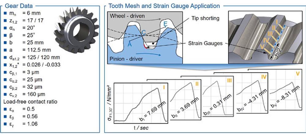
Figure 3 Test gear geometry and strain gauge application.
To investigate the tooth root stress, the gearing shown in Figure 3 with a center distance of a = 112.5 mm was used. This was designed and manufactured within the framework of the IGF project 18085/N1 for the measurement of tooth root strain by means of strain gauges (SG) in quasistatic (Ref. 15). The relatively large normal module of mn = 6 mm and the face width of b = 25 mm allow the application of a strain gauge chain with ten measuring points. This makes it possible to record the tooth root strain at different face width positions within one tooth mesh. The strain gauge chain was applied at the 30° tangent of the tooth root. The gear has a tip shortening of k∙mn = -2.5 mm. This is necessary to prevent damage to the strain gauges and the cabling in the root of the pinion. The pinion flank is modified with a lead crowning of cβ,1 = 3 μm. The gear is designed with a profile and lead crowning of cα,2 = 25 μm and cβ,2 = 32 μm. The manufacturing-induced twist is cv,2 = 160 μm.
The tip shortening and modifications to the wheel result in a reduced load-free overall contact ratio of εγ = 1.03. At a torque of MIn = 238 Nm, the overall contact ratio increases to εγ = 1.24. Due to the low overall contact ratio for a helical gear, a pronounced single tooth contact area and an increased vibration excitation occur during operation. A spur gear with a number of teeth z1,2 = 28, normal module mn = 4 mm, and pressure angle α = 18° was used as a reference gear set. The overall contact ratio of the reference gear is εγ = 1.595.
The measurement signals were transmitted in the test rig with the aid of a slip ring transmitter. Since its size increases with the number of transmission channels, the number of evaluated measuring points in the tooth root was limited to five, see Figure 3. The strain gauge chain was applied in such a way that the third measuring point is located in the center of the tooth. The face width positions of the individual strain gauges measured after application are shown in Figure 3. The tooth mesh starts at measuring point I at the active tooth root diameter of the pinion.
Test Setup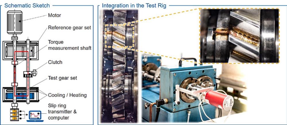
Figure 4 Test rig setup for the measurement of the tooth root strain.
The tooth root stress in operation was investigated on a back-to-back test rig according to DIN ISO 14635, see Figure 4 (Ref. 9). The test rig consists of a test gear set and a reference gear set, which are connected via a torque measuring shaft and a tension shaft with a clutch. By twisting the clutch, for example with the aid of a lever and weights, a torque can be generated in the power circle shown. The torque measuring shaft is used to measure the applied torque with calibrated strain gauges. The motor brings the test rig up to a defined rotational speed and only has to apply the losses of the gears, bearings, and seals. This makes this test concept very efficient since the drive power is only approx. 10% of the actual power in the power circle (Ref. 8).
The right part of Figure 4 shows the integration of the test gear into the test rig. The signal lines of the strain gauges on the pinion were led out of the test gear via a hollow shaft. By sealing the bore, the gearbox could be operated with splash lubrication. The slip ring transmitter was flanged to the end of the pinion shaft. The maximum test speed of the slip ring transmitter and thus of the entire test setup is limited to nIn = 2,000 min-1. To measure the tooth root stress during operation, the test rig was tensioned to different defined torques, each torque was controlled by means of a torque measuring shaft and the tooth root stress was recorded at various constant speed levels.
Evaluation of the Strain Measurement
The measurement of the tooth root strain by means of strain gauges is carried out with the Wheatstone measuring bridge. Each strain gauge in the tooth root was supplemented with a supplementary resistor on the pinion shaft to form a half-bridge, see Figure 5. The voltage across the supplementary and strain gauge resistors was transmitted via the slip ring transmitter for each measuring point. With five measuring points and three signal lines per strain gauge, a total of 15 channels are required for transmission. The voltage signals were recorded using the Labview software from National Instruments and internally supplemented to form a full bridge. Based on the change in resistance and the proportionality factor of the strain gauge chain, the strain at the strain gauge was calculated. For each time step, the strain was determined for the individual face width positions. In a subsequent step, the measured tooth root strain curves were converted into tooth root stress curves using Hooks law. Since the calculation methods of the quasistatic tooth contact analysis and the calculation methods in the MBS evaluate the tooth root stress over the pitch angle, it is necessary to transfer the measured data into the path domain for the comparison between calculation and measurement. For this purpose, the time steps of the measurement were converted into rolling angles using the formula shown in Figure 5. After the conversion, the tooth root stress related to the rolling angle for the face width positions is available.
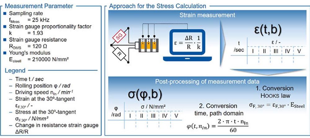
Figure 5 Conversion of the measured tooth root strain.
Simulation Model for the Calculation of the Dynamic Tooth Root Stress
The test rig presented in “Test Setup” and the test gear set used were mapped in the Simpack MBS. In the following chapter, the topology and the model structure of the simulation model are described, the contact pattern under load from the tooth contact analysis is compared to the contact pattern from the test rig and the influence of modified tip stiffnesses and damping on the tooth root stress is evaluated.
Topology and Model Design
The transfer of the test rig to MBS requires the simplification of the test rig. In the MBS, only rotating parts of the drivetrain are modeled. The shafts and couplings of the drivetrain are modeled as linear-elastic bodies with their eigenmodes. The test and reference gears are considered as rigid bodies. The dynamic excitation and vibration behavior of the gears is represented by the WZL GearForce6D user force, see Figure 6.
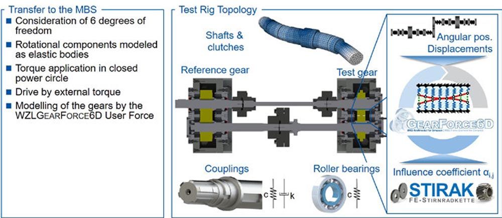
Figure 6 Transfer of the test rig to the MBS.
The dynamic tooth contact analysis GearForce6D was developed by Brecher et al. and is integrated into Simpack as a Fortran user force (Ref. 4). The calculation method uses the positions and rotation angles calculated by the MBS solver to completely define the contact conditions, see Figure 6. Based on these contact conditions, a penetration calculation is performed for the potential contact points. With the help of the previously calculated influence numbers and the penetrations, the spring model is solved, and the contact forces are converted to the gear centers. These forces and torques are finally transferred to the MBS solver (Ref. 4).
The coupling between gears and shafts as well as between shafts and clutches among each other is done with one degree of freedom in the direction of rotation. The coupling is parameterized as a torsion spring-damper element. The shafts are modeled with six degrees of freedom and constrained by the corresponding bearings. The bearing stiffness is calculated using the geometry data of the bearings in Simpack. The bearing damping is not taken into account. The load is applied by twisting the two clutch halves analogically to the real test rig. The angle of twist is adjusted iteratively until the desired torque is achieved in the power circle. The operating speed is specified by applying an external torque at a defined speed.
Comparison of Contact Pattern
An initial comparison of the simulation model and the test rig is made on the basis of the contact pattern under load. For this purpose, the loaded pinion flank in the test rig was colored with contact pattern paint and the contact pattern was recorded at increasing torque levels. The calculated contact pattern was calculated using the FE-Stirnradkette (Stirak). The results are compared in Figure 7. The drive torques MIn = 140, 336, and 483 Nm were considered.
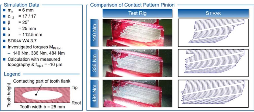
Figure 7 Comparison of contact patterns.
The contact pattern in the test rig shows unloaded areas of the tooth flank at the top left and bottom right for all torques considered. These are due to the high amounts of profile and lead crowning as well as the twist. In addition, it can be assumed that there is a misalignment of the two gear axes in the test rig since the contact pattern is shifted to the right at low loads. It was not possible to measure the actual axes positions in the test rig.
The right part of Figure 7 shows the contact pattern of the FE-Stirnradkette. The calculation was performed taking into account the measured flank topography at the wheel. The manufacturing deviations at the pinion are
The influence of the axes misalignment was approximated by a lead angle modification of fHβ,1 = –10 μm. The amount of correction was determined iteratively based on the contact pattern and tooth root stress at different width points. Also in the FE-Stirnradkette, the upper left and lower right regions of the tooth flank are not in contact. Furthermore, a shift of the contact pattern to the right-hand side can be seen. The contact patterns in the test rig and calculation agree to a good approximation. The deviations are due to the fact that the exact position of the axes relative to each other is unknown. The influence numbers required for the calculation using GearForce6D are determined on the basis of the microgeometry used for the comparison.
Influence of the Stiffness on the Dynamic Tooth Root Stress
The dynamic vibration behavior of powertrains is significantly influenced by the stiffnesses of the individual components and coupling points. The stiffnesses of the components, e.g., shafts, couplings and gears, are represented by elastic modeling. The stiffnesses and damping of the coupling points are specified by the user. Since uncertainties exist here, the influence of stiffness and damping on the tooth root stress at different speeds is considered. Figure 8 shows the calculated tooth root stresses from the multibody simulation (MBS) with rigid and elastic couplings. For the calculation of rigid couplings, the corresponding torsional degrees of freedom were constrained so that no relative torsion was possible. The elastic coupling points were modeled with a torsional stiffness of cspline shaft = 106 Nm/rad and cfeather key = 5∙105 Nm/rad as well as a torsional damping of k = 500 Nms/rad. The measuring points I and V are evaluated as examples.
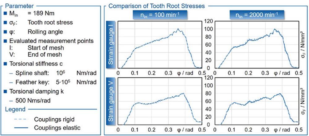
Figure 8 Impact of stiffness on the calculated tooth root stress.
At a quasistatic speed of nIn,1 = 100 min-1, no significant influence of the coupling points on the calculated tooth root stress is discernible. At an increased rotational speed nIn,2 = 1,500 min-1, an influence of the coupling points can be detected. However, the change in the tooth root stress is in the range of ΔσF
Comparison between Measured and Calculated Tooth Root Stresses
The comparison between measured and calculated tooth root stress is carried out in the area of quasistatics and in the area of dynamics. In quasistatics, the measured tooth root stress is compared to the calculated values of the MBS and the FE-Stirnradkette (Stirak). In the area of dynamics, only the results from measurement (SG) and MBS calculation are compared. The tooth root stress of the respective measuring points from the calculation is interpolated using the face width positions presented in “Test Gear and Strain Gauge Application,” since the resolution of the FE mesh does not match with the exact face width positions.
Quasistatic
Figure 9 shows the tooth root stresses from the measurement (SG), the MBS and the FE-Stirnradkette for the measuring points I, II, IV and V. The measuring point III is not considered, since an increased measurement noise occurred here due to a defect in the measurement chain of the strain gauge.
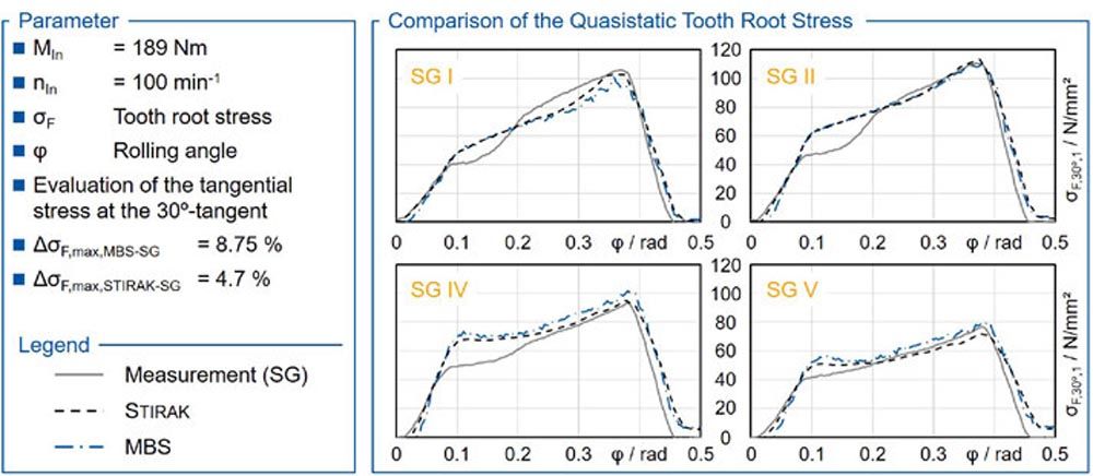
Figure 9 Comparison of the calculated and measured tooth root stress in quasistatics.
The calculated tooth root stresses from the MBS and the FE-Stirnradkette agree with regard to course and maximum value for all measuring points. This was to be expected, since the MBS method has already been verified using the FE-Stirnradkette and the point clouds of the gear teeth used are identical. Differences occur between the calculated and measured tooth root stresses. In particular, at the beginning of tooth mesh between 0.2 rad F,max,MBS-SG = 8.75 N/mm² and between FE-Stirnradkette and measurement σF,max,Stirak-SG = 4.7 N/mm². These deviations are ΔσF
Influence of the Rotational Speed
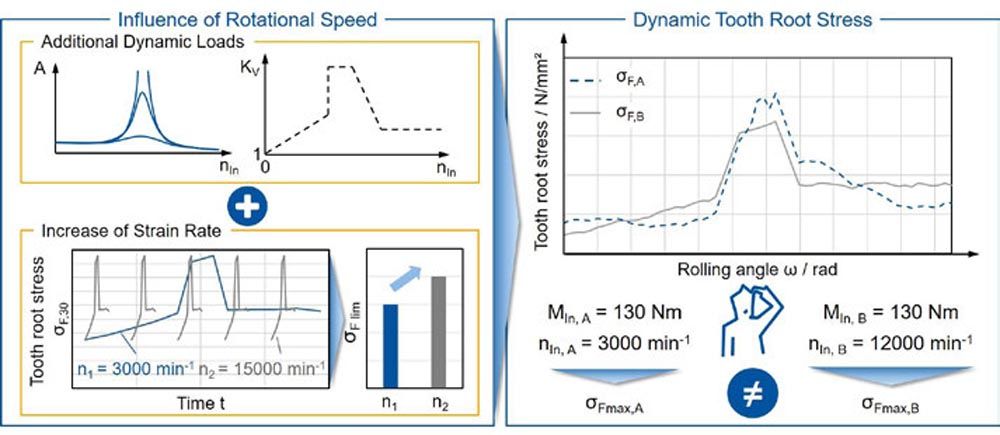
The influence of the rotational speed on the dynamic tooth root stress in measurement and MBS is shown in Figure 10. The upper diagrams show the tooth root stresses at the speeds n1 = 100 min-1 and n2 = 1,500 min-1 over the tooth mesh for the measuring point II. The measurement shows that the tooth root stress increases at the increased speed n2 in the region of the start of mesh at φ = 0.1 rad and decreases in the region of the maximum tooth root stress at φ = 0.35 rad. The tooth root stress of the MBS simulation also shows a similar curve.
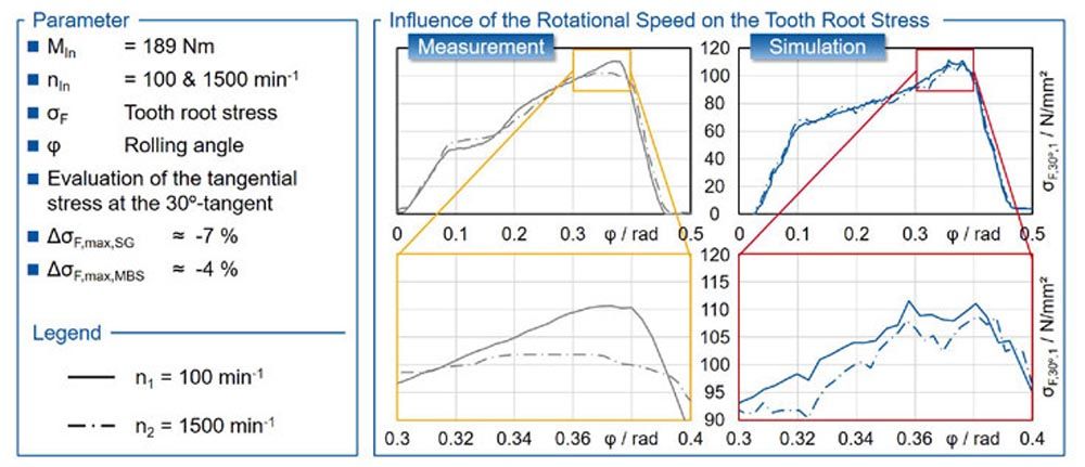
Figure 10 Comparison of calculated and measured tooth root stress at variable speeds.
The lower diagrams show the section of the maximum tooth root stress at 0.3 rad Meas. = 8.8 N/mm² or ΔMeas. ≈ 7% due to the dynamics. This can be explained by the subcritical operation points from the measurements. Only in the main resonance the excitation of the drivetrain, which corresponds to maximum tooth root stress, and the additional dynamic load occur at the same moment. In the MBS, the effect is less pronounced with a decrease of ΔσMBS = 5 N/mm² or ΔMBS ≈ 4%. The fundamental influence of the rotational speed on the dynamic tooth root stress is represented by the MBS. The differences can be attributed, among other things, to the fact that in the measurement, imbalances, pitch errors, and radial runout have an influence on the vibration behavior. These influences are not yet mapped in the MBS.
Summary and Outlook
The investigation of the strain rate influence on the tooth root load capacity requires the consideration of different speeds in the test. Due to the speed-dependent excitation, it is to be expected that the maximum tooth root stress will be different at different speeds due to the dynamics. Before determining the tooth root load capacity in the test, it must therefore be ensured that the influence of the strain rate on the tooth root load capacity is not superimposed by the influence of the dynamics. In order to differentiate between these influences on the stress and load capacity in the tooth root, a validated method for calculating the local and time-related tooth root stress at variable operating points, taking dynamics into account, is required.
The aim of the report is to validate the calculation of the local, time-related tooth root stress curves. For this purpose, the tooth root stress is measured in operation with the help of strain gauges and compared with the calculated values. In the first step, the test rig as well as the measurement setup and procedure for determining the tooth root stress in operation are presented. In the second step, the test setup is transferred to the multibody simulation Simpack and the influence of the coupling stiffness on the tooth root stress in operation is evaluated. In the third step, the tooth root stresses calculated in Simpack are compared with the measured values in the area of quasistatics and dynamics and the calculation of dynamic tooth root stresses in the multibody simulation is validated.
The measurement of the tooth root stress in operation was carried out with the help of strain gauges in the tooth root on a back-to-back test rig. The transmission of the measurement signals was carried out by a slip ring transmitter, which limited the maximum speed of the test set-up to nIn = 2,000 min-1. The real position of the strain gauges in the tooth root was measured and taken into account in the evaluation of the calculated tooth root stresses. The measured strain in the tooth root in the time domain is converted into a tooth root stress in the path domain.
The test setup is transferred to the multibody simulation Simpack. There, the shafts and couplings are modeled as elastic bodies with their eigenmodes. The coupling points, e.g., between gear and shaft or between coupling and shaft, are modeled by torsion-spring-damper elements. The gears and their characteristic excitation are represented by GearForce6D. This also enables the calculation of the dynamic tooth root stress taking into account the dynamic displacements and loads. The comparison of the contact patterns under different loads does not show any significant differences between test rig and simulation. The coupling parameters torsional stiffness and torsional damping have no significant influence on the calculated maximum tooth root stress and the course over the mesh at the operating points considered outside the resonance points.
The quasistatic comparison between the measured tooth root stresses and those calculated in the FE-Stirnradkette and the MBS at nIn = 100 min-1 shows a high level of agreement in the area of the maximum tooth root stress. In the dynamic range at nIn = 1,500 min-1, the measurement shows an increase in the tooth root stress in the area of the mesh start and a decrease at the maximum tooth root stress compared to the quasistatic case. The tooth root stress calculated in the MBS also reproduces this effect. However, the decrease of the maximum tooth root stress in the MBS with ΔMBS ≈ -4% is about half as large as in the measurement with ΔMeas. ≈ -7%. This is due, among other things, to imbalances, pitch and runout errors that are not taken into account in the MBS.
The results of the analyses show a high level of agreement between the calculated and measured tooth root stresses, both in quasistatic and dynamic operation. The calculation of the dynamic tooth root stress with the help of the MBS was successfully validated. GearForce6D can be used for the simulation of different test rigs or operating points to investigate the strain rate influence and enables the quantitative evaluation of the speed influence on the maximum tooth root stress at the operating point. The next step is the investigation of the strain rate dependency of the tooth root fatigue strength of gears regarding different operating speeds.
Acknowledgement
The authors gratefully acknowledge financial support by the German Research Foundation (DFG) [Ref.-Nr. DFG EXC2023/1—B1.II], the WZL Gear Research Circle and the Clean Sky 2 JU (Ref. No. 831832) within the Horizon 2020 Programme of the European Commission for the achievement of the project results. 
References
- Bathias, C.; Paris, P.: Gigacycle fatigue in mechanical practice. New York: Marcel Dekker, 2005.
- Baud, S.; Velex, P.: Static and Dynamic Tooth Loading in Spur and Helical Geared Systems-Experiments and Model Validation. In: J. Mech. Des., 124. Jg., 2002, Nr. 2, S. 334–346.
- Bosch, M.: Über das dynamische Verhalten von Stirnradgetrieben unter besonderer Berücksichtigung der Verzahnungsgenauigkeit. Diss. RWTH Aachen University, 1965.
- Brecher, C.; Brimmers, J.; Westphal, C.: Einfluss der dynamischen Lastverteilung in Zahnkontakten auf das Systemverhalten. In: Tagungsband zum Dresdner Maschinenelemente Kolloquium DMK 2019 Dresdner Maschinenelemente Kolloquium DMK 2019. Dresden, 26–27 November 2019, S. 353–372.
- Brecher, C.; Brimmers, J.; Trippe, M.: Einfluss der Dehnrate auf die Tragfähigkeit bei Hochdrehzahlanwendungen. In: Tagungsband zum Dresdner Maschinenelemente Kolloquium DMK 2019 Dresdner Maschinenelemente Kolloquium DMK 2019. Dresden, 26–27 November 2019, S. 321–341.
- Bretl, N.: Einflüsse auf die Zahnfußtragfähigkeit einsatzgehärteter Zahnräder im Bereich hoher Lastspielzahlen. Aachen: Shaker, 2011.
- Carl, C.: Gehörbezogene Analyse und Synthese der vibroakustischen Geräuschanregung von Verzahnungen. Diss. RWTH Aachen University, 2014.
- Ciulli, E.: Experimental rigs for testing components of advanced industrial applications. In: Friction, 7. Jg., 2019, Nr. 1, S. 59–73.
- Norm DIN 14635-1 (2006) Zahnräder—FZG-Prüfverfahren—Teil 1.
- 1Norm DIN 3990 Teil 1 (Dezember 1987) Tragfähigkeitsberechnung von Stirnrädern. Einführung und allgemeine Einflußfaktoren.
- Donath, B.: Berechnung der inneren dynamischen Zahnkräfte ein- und zweiflankiger Zylinderradgetriebe mit Schrägverzahnung. Diss. TU Dresden, 1983.
- Eberhard P.; Ziegler P.: Berechnung von dynamischen Spannungen und Kontaktkräften ind. Abschlussbericht zum Forschungsvorhaben FVA-Nr. 950, Heft 927, Forschungsvereinigung Antriebstechnik e.V., Frankfurt a.M., 2011.
- Emde, T.: Mechanisches Verhalten metallischer Werkstoffe über weite Bereiche der Dehnung, der Dehnrate und der Temperatur. Diss. RWTH Aachen University, 2009.
- Früh, P.: Dynamik von Zahnradgetrieben. Modellbildung, Simulation und experimentelle Analyse. Diss. Universität Rostock, 2008 7–18 WZL Conference USA.
- Forschungsvereinigung Antriebstechnik e.V.: Abschlussbericht Lokale Biegewechseltragfähigkeit. Lokale Zahnfußtragfähigkeit von Stirnrädern bei Biegewechsellast, Heft 1280, Forschungsvereinigung Antriebstechnik e.V., Frankfurt am Main, 2018.
- Gacka, A.: Entwicklung einer Methode zur Abbildung der dynamischen Zahneingriffsverhältnisse von Stirn- und Kegelradsätzen. Diss. RWTH Aachen University, 2013.
- Geiser, H.: Grundlagen zur Beurteilung des Schwingungsverhaltens von Stirnrädern. Diss. TU München, 2002.
- Gerber, H.: Innere dynamische Zusatzkräfte bei Stirnradgetrieben. Modellbildung, Innere Anregung und Dämpfung. Diss. TU München, 1984.
- Gold, P.: Statisches und dynamisches Verhalten mehrstufiger Zahnradgetriebe. Diss. RWTH Aachen University, 1979.
- Gwinner, P.: Schwingungsarme Achsgetriebe elektromechanischer Antriebsstränge. Auslegung schwingungsarmer Stirnradverzahnungen für den automobilen Einsatz in hochdrehenden, elektrisch angetriebenen Achsgetrieben. Diss. Technische Universität München (TUM), 2017.
- Heider, M.: Schwingungsverhalten von Zahnradgetrieben. Beurteilung und Optimierung des Schwingungsverhaltens von Stirnrad und Planetengetrieben. Diss. TU München, 2012.
- Norm ISO 6336 Teil 1 (November 2019) Calculation of load capacity of spur and helical gears.
- Linke, H.: Untersuchungen zur Ermittlung dynamischer Zahnkräfte von einstufigen Stirnradgetrieben mit Geradverzahnung. Diss. TU Dresden, 1969.
- Mayer, H.: Fatigue crack growth and threshold measurements at very high frequencies. In: Int. Mater. Rev., 44. Jg., 1999, Nr. 1, S. 1–34.
- Möllers, W.: Parametererregte Schwingungen in einstufigen Zylinderradgetrieben. Einfluß von Verzahnungsabweichungen und Verzahnungssteifigkeitsspektren. Diss. RWTH Aachen University, 1982.
- Müller, R.: Schwingungs- und Geräuschanregung bei Stirnradgetrieben. Diss. TU München, 1991 Dynamic Tooth Root Stresses 7–19.
- Niemann, G.; Winter, H.: Maschinenelemente. Band 2: Getriebe allgemein, Zahnradgetriebe - Grundlagen, Stirnradgetriebe. Bd. Nr. 2, 2. Aufl. Berlin: Springer, 2003.
- Nonaka, I.; Setowaki, S.; Ichikawa, Y.: Effect of load frequency on high cycle fatigue strength of bullet train axle steel. In: Int. J. Fatigue, 60. Jg., 2013, S. 43–47.
- Pyttel, B.; Schwerdt, D.; Berger, C.: Very high cycle fatigue—Is there a fatigue limit? In: Int. J. Fatigue, 33. Jg., 2011, Nr. 1, S. 49–58.
- Rettig, H.: Dynamische Zahnkraft. Dissertation Technische Hochschule München, 1957.
- Schneider, N.; Pyttel, B.; Berger, C.; Oechsner, M.: Influence of Frequency and Testing Technique on the Fatigue Behaviour of Quenched and Tempered Steel in the VHCF-Regime. In: Adv. Mater. Res., 891–892. Jg., 2014, S. 1430–1435.
- Schurer, S.: Einfluss nichtmetallischer Einschlüsse in hochreinen Werkstoffen auf die Zahnfußtragfähigkeit. Diss. Technische Universität München (TUM), 2016.
- Felix Stoffels: Rolls-Royce sucht beim Triebwerk den Quantensprung. https://www.aerotelegraph.com/rolls-royce-getriebe-triebwerk-power-gearbox-was-ist-eigentlich-der-ultrafan [Stand: 03.03.2020].
- Weck, M.; Winter, H.; Winkler, A.; Rettig, H.: Innere dynamische Zusatzkräfte an Zahngetrieben. 1. Abschlussbericht zum Forschungsvorhaben FVA-Nr. 7, Heft 22, Forschungsvereinigung Antriebstechnik e.V., Frankfurt a.M., 1975.
- Winkler, A.: Über das dynamische Verhalten schnellaufender Zylinderradgetriebe. Diss. RWTH Aachen University, 1975.