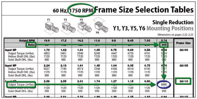
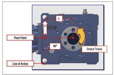
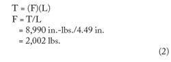
Using values from the manufacturer’s specifications (Figures 2 and 3 for our example), you can calculate the resultant force acting at the pivot point as follows:
In essence, the connection method at the pivot point you chose (i.e., bolt, threaded rod, etc.) must be able to withstand this calculated force when in tension. If you find that the calculated force exceeds the physical limits of the connection method, you may choose to incorporate a different, stronger material for the torque arm.
A way to minimize this force is to increase the distance L of the pivot point, as shown in Figures 5 and 6. In these examples, the reducer has a T-type torque arm mounted to it, which moves the pivot point an additional 1.85 inches farther from the center of the reducer’s bore.
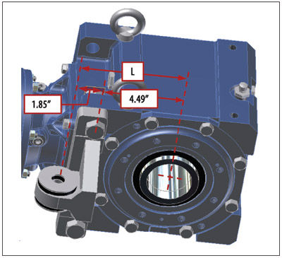
Figure 5—In this example, the reducer has a T-type torque arm mounted to Figure 5—In this example, the reducer has a T-type torque arm mounted to it, which moves the pivot point an additional 1.85 inches farther from the center of the reducer’s bore.
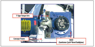
Figure 6—A shaft-mounted speed reducer in a conveyor application with a T-type torque arm.
If all other factors remain the same, this increase in distance yields a decrease of nearly 600 pounds in the force on the torque arm.
Thus:
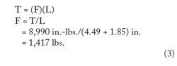
Once again, this calculated force must be compared to the yield stress of the torque arm material to assure that the material limitations are not exceeded.
A Turnbuckle for a Torque Arm
Provided that it will fit within the design constraints of your application, you may opt to use a turnbuckle for a torque arm. A turnbuckle is a device commonly used to tighten a rod or rope. Its components include a sleeve with screwed connections of opposite hands (left and right) at each end. Upon turning the sleeve, the connected parts (threaded rods) will be drawn together, taking up slack and producing tension (Fig. 7).
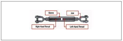
Figure 7—A typical turnbuckle.
You can calculate the force acting at the pivot point in this situation using the same formula for force as in the previous examples. Figures 8-9 show a typical mounting style for a turnbuckle torque arm.
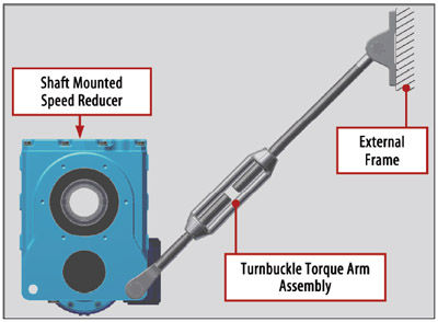
Figure 8—A typical mounting style for a turnbuckle-style torque arm.
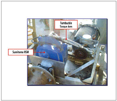
Figure 9—A turnbuckle-type torque arm being used on a Sumitomo helical shaft mount unit.
A Note About Mounting Hardware
In addition to assuring that the forces acting on the torque arm itself do no exceed the limitations of the torque arm material, you must also consider the effects of the force on the mounting hardware (nuts, bolts, etc.).
When taking this into account, you must note that the force is not acting on the hardware in tension, but rather in shear. Depending on the location of such hardware, bending movements induced by the force may also be acting on the hardware.
Hardware manufacturers usually provide yield and shear limitations for their products. Once again, it is important to compare the calculated forces/stresses acting on the hardware against the published limiting values to assure that the critical points are not exceeded.
A Note About Reversing Rotation
In reversing applications, the output of the SMSR rotates in one direction for a period of time, and then reverses and rotates in the opposite direction for a period of time. This application type requires considering the compressive forces that the torque arm must also bear.
Recalling that, ideally, a torque arm is mounted so it is in tension, in a reversing application, the torque arm may see a period of time when it also receives compressive forces. Such compressive forces, if great enough, could buckle the torque arm. For such applications, designers may want to add a second torque arm on the opposite side of the SMSR. The second torque arm would take the tension forces generated by the reverse rotation while minimizing the compressive forces on the first torque arm.
Angles Other Than 90°
Although it is important to maintain a pivot point at 90° to the center of the SMSR output hub, it may not always be possible due to limitations in the machine onto which the SMSR will be mounted. This is not uncommon, and reducer manufacturers who supply turnbuckle torque arms with their SMSR units often note that the torque arm may be mounted with an angular variation, such as ±15°.
In such situations, the designer needs to evaluate the effects of the resultant forces acting on the torque arm. Figure 10 shows a torque arm mounted to an SMSR at some angle (è) that is less than 90°.
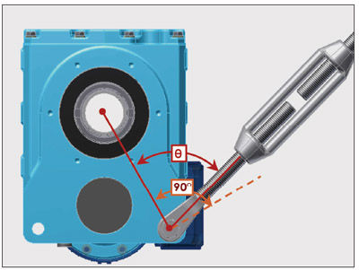
Figure 10—A torque arm mounted to an SMSR at less than 90°.
Because the torque arm is not acting at a 90° angle to the output bore of the SMSR, there are two forces acting on it. The free-body diagram in Figure 11 details these forces.
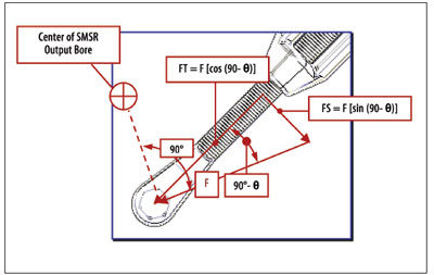
Figure 11—When a torque arm is mounted at an angle other than 90°, force F is composed of both tension (FT) and shear (FS) forces. Both must be considered when evaluating the strength of the torque arm design.
The resultant forces (FT and FS) are the component forces of Force “F” acting on the torque arm. These resultant forces place not only a force in tension (FT) acting on the torque arm, but also a shear force (FS). Both forces must be considered when evaluating the strength of the torque arm design.
The Effect of Shaft Runout
Despite a high degree of accuracy in manufacturing processes, shaft runout sometimes occurs. Such runout (on the driven shaft) may cause the reducer to “wobble” on the shaft during operation. This could be particularly troublesome if the torque arm is rigidly mounted to the anchor point. A rigidly mounted torque arm attached to an SMSR driving a shaft with a high degree of runout may result in (among other things) a broken driven shaft, cracks at the anchor point, a decrease in the life of the output bearings of the SMSR and/or the conveyor and lubrication leakage. Introducing some “float” in the torque arm at the anchor point will counteract these problems.
Float may be introduced at the pivot point by attaching rubber bushings to the pivot and anchor points, as shown in Figure 12.
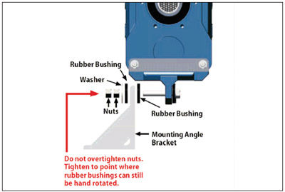
Figure 12—Rubber bushings installed at the anchor point and/or pivot point will provide “float” to compensate for runout in the driven shaft.
If dual rotation of the output shaft is possible in the application, manufacturers recommend installing rubber bushings on both sides of the pivot and anchor points so float is possible regardless of the direction of rotation.
A loose clearance designed between the bolts and through holes in the torque arm bracket may also assist in creating float.
In addition to taking precautions to eliminate a rigid mount, designers must also ensure the torque arm is properly aligned when mounting it to the SMSR. Misalignment may inadvertently cause binding that could decrease or entirely eliminate this float.
Conclusion
Although seemingly simple in concept, a torque arm is an important component when considering a shaft-mounted speed reducer for an application. Before selecting a potential torque arm design, designers should evaluate the offering supplied by the manufacturer of the shaft-mounted speed reducer. In doing so, they may determine that the standard offering fits into the application constraints. Additionally, some manufacturers offer more than one standard design (i.e., turnbuckle, T-type) to meet a variety of applications. However, if the existing available designs fail to meet the established application criteria, following the methodology detailed in this article will help to develop a functional and robust torque arm design.
Todd R. Bobak has worked in the gear industry for 15 years. He has held positions in technical service, design and development, and quality assurance. He is a product engineer for Sumitomo Drive Technologies in Chesapeake, VA.