[advertisement]

April 1, 2021


Applications Food Components Couplings Ask the Expert Product News Technical Articles

Problem with Disk Pack Coupling

Ask the Expert

THE QUESTION

I have a problem with a disc flexible shaft coupling that is used in screw compressors. This coupling is cracked and damaged after a short time, and the changing rate of this coupling is very high — about every 3 months. But as I understand from the machine manual, the coupling replacement may be every 8,000 hours or 12 months. I checked the alignment by laser alignment device; it was okay, but the problem still exists. I observed a similar deflection/buckling on it after 3 months in operation. (I would be most grateful) if you could please advise me about this issue..


EXPERT RESPONSE PROVIDED BY Robert Errichello.

Features of Disk Pack Couplings

Disk pack couplings are popular couplings because they offer several attractive features::

  • Compact with high torque capacity
  • Require no lubrication
  • Disk packs can be visually inspected without disassembly
  • Disk packs can be visually inspected with a strobe light while running
  • Disk packs can be removed and replaced without removing hubs from shafts
  • Failing disks are easily visually detected
  • Offer high torsional rigidity and no backlash

However, there are limitations

  • Limited misalignment capability
  • Limited fatigue life due to bending stresses in the disk packs
  • High misalignment shortens the fatigue life
  • Little or no vibration damping

What to do when disk pack couplings fail

Share and save:


This article appeared in the April 2021 issue.


Read PDF

[advertisement]

The first step is to determine whether your disk pack coupling is appropriate for the application, and confirm that it has adequate load capacity. Start by asking the coupling manufacturer to send their service representative to review your application and help you determine whether you have the right coupling for the application. Disk pack couplings come in a variety of types including close-coupled or spacer-couplings, single-flexing or double-flexing, semi-floating or full-floating shaft, and hollow or solid shaft. Once it is confirmed that you have the right coupling type, the next step is to determine whether the coupling size is proper.

Service factor must be large enough

The service factor is a multiplier applied to the normal operating torque to account for the load characteristics of the driving and driven equipment. Besides the normal operating torque, the service factor must be large enough to accommodate harsh duty such as high peak loads or frequent starts and stops. The coupling manufacturer’s catalog rating for the disk pack coupling must be greater than the calculated value of the normal operating torque times the service factor.

Service factors have evolved from experience that is based on past failures (Ref. 1). That is, after a coupling failed, it was determined that by multiplying the normal torque by a factor and then sizing the coupling, the coupling would not fail.

Service factors are used to account for higher torque conditions of the equipment to which the coupling is connected. In API 671, a recommended service (or experience) factor of 1.5 times normal torque is applied for special purpose couplings for refinery service (Ref. 2).

Most manufacturers of disk pack couplings recommend a service factor of 1.5 minimum. However, catalog rating procedures and recommended service factors vary widely, and it is important to follow and use the ratings and service factors recommended by the actual coupling manufacturer and not intermix them with other manufacturer’s rating procedures and service factors.

Startup torque accumulates fatigue damage

Peak torque typically occurs during startup when the driver accelerates the torsional system up to its operating speed. An induction motor is capable of an overload torque of at least three times the normal operating torque. A particularly harsh startup torque occurs with a synchronous electric motor. The startup of synchronous motor driver is usually associated with torsionally excited vibrations and low-cycle fatigue problems. The frequency of these torsional impulses is twice the line frequency at zero speed, and the frequency decreases linearly as speed increases. At synchronous speed the frequency of the impulses becomes zero. As the speed increases during a start, the frequency of the impulses coincides, for a moment, with the lowest natural frequency of the torsional system. During the resonance, the magnitude of the torsional oscillations can develop an overload torque of six times the normal operating torque. Depending on how fast the motor can pass through the critical speed, the coupling will accumulate several cycles of fatigue damage. Unfortunately, disk pack couplings do not provide much damping to limit the dynamic oscillations associated with system resonance. Consequently, frequent starts increase the risk of fatigue failure, and it is prudent to limit the number of starts of a synchronous motor.

Check the alignment of the coupling

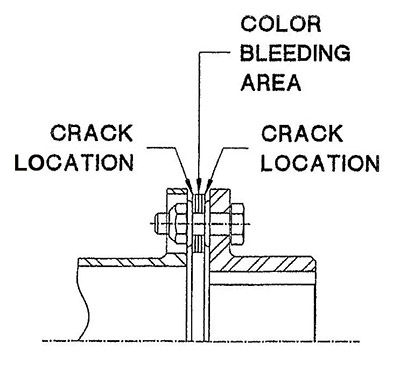
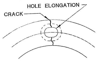
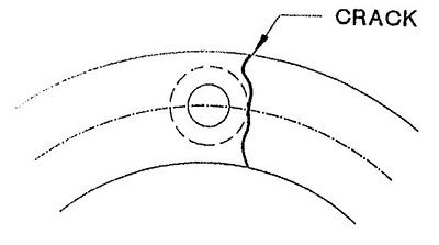
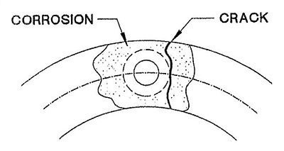
The most common failure of a disk pack coupling is fatigue of the disk pack due to excessive misalignment (Ref. 1). This is usually caused by poor initial alignment of the connected machines. However, it can also be caused by operating conditions. Changes from initial alignment can occur because of bearing wear, settling of foundations, loose anchor bolts, pipe strain, and base distortion due to torque, thermal deformation, and vibrations in connected machines. Alignment checks should be made under cold startup temperature and after the connected machines are at hot operating temperatures. If there is large thermal deformation, it might be necessary to bias the cold alignment to compensate for thermal deformation. The following list describes typical issues with installed disk pack couplings that can lead to failed disk packs (Ref. 2).

[advertisement]

Ideally the disk pack should be centered in a neutral position where it remains flat and parallel with the end flanges. However, even if the disk packs look ideal after the initial alignment, the disk packs might distort under operating conditions. Therefore, it is important to inspect the installed couplings.

What to look for when inspecting installed couplings

  1. Reddish brown color bleeding out between disk laminations at the outside diameter (OD) of the disk pack. This indicates fretting corrosion due to loose bolts or chemical attack. See Figure 1.
  2. Fine line crack starting in the outer disk tangent to the washer (OD). This indicates a fatigue failure due to excessive misalignment. See Figure 1.
  3. Figure 1: Fatigue failure due to excessive misalignment.
  4. The disk pack is wavy and the dimension “N” between flange faces is smaller than indicated on the installation instructions or applicable assembly drawing as shown in Figure 2. The coupling has been installed in a compressed condition or equipment has shifted axially during operation. Check for thermal growth problems. If the application has a sleeve-bearing motor, make sure that the operating centerline of the motor rotor is properly positioned. Realign the axial position of the equipment to relieve disk pack compression during operation.
  5. Figure 2: The disk pack is wavy and the dimension “N” between flange faces is smaller than indicated on the installation instructions or applicable assembly drawing.
  6. The disk pack is wavy and the dimension “N” between flange faces is larger than indicated on the installation instructions or applicable assembly drawing as shown in Figure 3. The coupling has been installed in an elongated condition or equipment has shifted axially during operation. Realign the axial position of the equipment so that the coupling operates with a neutral flat disk pack. If the application has a sleeve-bearing motor, make sure that the operating centerline of the motor rotor is properly positioned.
  7. Figure 3: The disk pack is wavy and the dimension “N” between flange faces is larger than indicated on the installation instructions or applicable assembly drawing.
  8. Wavy disk packs on both ends of the coupling. One end is compressed, and the other is elongated. See Figure 4. This is called “oil canned” disk packs. The disk pack has no neutral center where it remains flat and parallel with the end flanges. Loosen all locknuts, correct the axial spacing, and tighten the locknuts. If this doesn’t resolve the problem, the disk packs might have been permanently deformed. Replace the disk packs and reassemble the coupling.
  9. Figure 4: Wavy disk packs on both ends of the coupling. One end is compressed, and the other is elongated.

Inspect failed couplings

It helps to show the coupling manufacturer’s service representative failed disk packs. Service representatives know the failure modes for disk packs, and specimens of failed disk packs might help in diagnosing the root cause of failure. By understanding the root causes of failures, remedies can be applied, and failures can be prevented in the future.

The following list describes the failure modes that typically occur in disk pack couplings, the root causes of failure, and the remedies (Ref. 2).

What to look for when inspecting failed couplings

  1. The disk is broken through the bolt hole as shown in Figure 5. This indicates loose coupling bolts. Replace the disk pack and tighten locknuts to the specified torque.
  2. Figure 5: The disk is broken through the bolt hole.
  3. Disks are embedded in the bolt body. This is usually the result of a loose bolt or severe torque overloads. This can also appear when turning the bolt during installation. Replace the bolt and tighten the locknut to the specified torque. Do not turn the bolt during the locknut tightening process. See Figure 6.
  4. Figure 6: Do not turn the bolt during the locknut tightening process.
  5. Disk is broken adjacent to washer face. Cracks usually start in the outermost disk and progress through the disk pack. This indicates excessive misalignment during operation. See Figure 7. Replace both disk packs and realign the equipment. Make a hot check of alignment to ensure it is within the coupling specification.
  6. Figure 7: Excessive misalignment during operation.
  7. Disk is broken adjacent to washer face with fretting corrosion in the area of the crack. This indicates excessive misalignment during operation. See Figure 8. Replace both disk packs and realign the equipment. Make a hot check of alignment to ensure it is within the coupling specification.
  8. Figure 8: Disk is broken adjacent to washer face with fretting corrosion in the area of the crack. This indicates excessive misalignment during operation.
  9. The disk pack has a bulge between the bolts, or is bowed toward one flange in alternate chord positions as shown in Figure 9, bolts are bent, or bolts are damaged as shown in Figure 6. This condition is a result of a large torque overload induced into the system above the peak overload capacity of the coupling. The remaining disk pack chordal sections will be very straight and tight. If the bulge appears in only one chordal section, there might be a loose bolt on one side of the distortion. Loosen all locknuts and unseat the bolts. The bulge should release and flatten out. If so, retighten the locknuts. If the distortion does not disappear, replace both disk packs and retighten the locknuts. If there is a synchronous motor driver, measure the startup torque at the motor shaft with strain gages to determine if torsional resonance causes overload torque that exceeds the peak torque capacity of the coupling. Check the coupling selection and apply the proper size and type of coupling for the characteristics of the application.
  10. Figure 9: The disk pack has a bulge between the bolts, or is bowed toward one flange in alternate chord positions.

Remedy for failed disk pack coupling

If the answer is yes for the entire following list of questions, and no adverse operating conditions have been discovered, it indicates that a greater service factor is required for your application, which means a larger disk pack coupling is required. Alternatively, the coupling might need to be changed to a different style with larger load capacity such as a flexible gear coupling.

  1. Has the manufacturer’s service representative confirmed that the coupling is the correct type for the application?
  2. Has the service factor been calculated?
  3. Has the peak torque been measured?
  4. Has the cold and hot alignment been measured?
  5. Has the installed couplings been inspected for proper disk pack deformation?
  6. Has the failed coupling been inspected for root cause of failure?

Robert Errichello is a gear consultant, teacher, and writer with over 50 years of industrial experience and over 40 years specializing in failure analysis

References

  1. Mancuso J.R., “Couplings and Joints- Design, Selection, and Application,” Marcel Dekker Inc., 2nd Ed., 1999.
  2. Calistrat, M.M., Flexible Couplings- Their Design, Selection and Use,” Caroline Publishing, 1994.


[advertisement]