The test parameters are specified (Table 1) where ωHS, ωLS, τHS and τLS are the angular velocity and torque of the high-speed input and low-speed output shafts respectively, and POUT is the power dissipated by the load. Each phase is run for 24 hours and the test is concluded once any abnormal behavior is detected, such as a change in sound or a substantial increase in current draw. The gear-heads are inspected periodically between phases to identify the onset of lubricant or mechanical failure. Phase 1 is a break-in period at no-load, Phase 2 is at the rated speed of the 20/1 gear-head, and Phase 3 is at 2× the rated speed. In phases 2 and 3, the load is increased incrementally until the motor torque reaches its maximum- rated continuous torque (17 mNm uncooled) (Ref. 5) and in phase 4 the speed is increased incrementally while the motor torque is held at 17 mNm.
Gear-Head Failure Modes and Probable Causes
The destructive test sequence described in Table 1 is conducted for the 20/1 planetary gear-head and each Orbitless gear-head version. Upon failure, each gear-head is disassembled, inspected, and the symptoms are documented. The onset of failure is detected with the planetary gear-head during Phase 4a at 12,000 rpm, which is expected after applying a reasonable safety margin to its 5,000 rpm manufacturer-specified speed rating. In Table 2, the test phase when failure occurred, the failure mode and the post- failure observations are tabulated for all gear-heads.
A post-failure inspection of the Version 1 Orbitless gear-head shows wear patterns on the journals where they align with the lateral faces of the bushings. The clockwise tooth face of the V1 sun gear is also visibly worn. Wear patterns on the carrier faces suggest that the planets contacted the carriers as a result of the conical bushing wear that was also observed. A post-failure inspection of the Version 2 Orbitless gear-head shows spalling and separation of the carrier mounted ball bearings.
The pre-mature bearing failures of Versions 1 and 2 are attributed to the planet bearings being mounted to the carriers. Since the applied bearing forces are lateral to tooth force, a yaw torque develops on the planets which causes bushing, tooth and lubricant wear in V1, and outright bearing failure in V2. This is illustrated (Fig. 5) where the upper planet axis engages the drive carrier and the lower planet axis engages the reaction carrier.
Figure 5 Orbitless planet forces and induced yaw torque.
The ball-bearings are more robust to yaw torque and increase the load capacity of V2 over V1 by approximately 40%. Mounting the bushings in the planets in V3 vertically aligns all forces, eliminates planet yaw torque, and increases load capacity to a level comparable with the planetary gear-head. It is proposed that load capacity may be further increased by mounting ball-bearings in the planets although space constraints may require a higher reduction ratio since that would introduce larger planet pinions.
The failure mode of the V3 Orbitless gear-head parallels that of the planetary gear-head. In both cases the test was stopped due to a change in sound quality, but no post-failure physical damage or wear was identified other than the initial signs of lubricant separation. In both cases the gear-head remains operational.
Efficiency Measurements
Efficiency values are derived by intermittently recording the current drawn by the motor IM during each 24 hours test cycle and computing the average. The total power input to the system PIN is separated into electrical losses PELEC, mechanical losses PMECH, and power delivered to the load POUT, as shown (Eq. 7). Electrical power losses are separated into impedance losses associated with the controller PC and motor windings PW,and mechanical power losses are separated into friction losses associated with the motor PM and gear-head PG, as shown (Eq. 8).
Load power POUT is taken from Table 1. Motor friction losses PM are computed (Eq. 9) where CM is the manufacturer-specified (Ref. 5) motor friction constant in (mNm/rpm), and gear-head losses PG are computed (Eq. 10) by subtracting the motor friction losses PM and load power POUT from the total mechanical power produced by the motor windings.
In Equation 10, KM is the manufacturer-specified (Ref. 5) motor torque constant in (mNm/A), IM is the measured motor winding current, ωHS is the motor speed, and the product KMIMωHS is the total mechanical power produced by the motor windings.
Motor winding losses PW are computed (Eq. 11) where RM is the manufacturer-specified (Ref. 5) winding resistance in (Ω). Controller losses PC are computed (Eq. 12) where PW + PMECH + POUT is the total power delivered by the controller and ηC is the manufacturer-specified (Ref. 6) controller efficiency in (%).
Equations 7–12 are used to derive gear-head efficiency ηG (Eq. 13) and total system efficiency ηSYS (Eq. 14).
Examples of raw current measurements for Phases 2c and 3f for the planetary 20/1 and Orbitless V3 gear-heads are shown (Fig. 6). The mean value over the entire 24 hour period is also computed and shown for each successfully completed phase.
Figure 6 Raw (left) and mean (right) current measurements.
For each mean current, the individual power components are computed from equations (7–12), and gear-head and total system efficiency are computed from Equations 13–14 and plotted (Figs. 7 and 8).
Figure 7 Gear-head power losses and efficiency.
Figure 8 Total system power losses and efficiency.
The largest recorded improvement occurs at 5 W and 5,000 rpm where the planetary 20/1 gear-head demonstrates efficiencies of ηG = 71% (gear-head) and ηS = 46% (system), and the Orbitless V3 gear-head demonstrates efficiencies of ηG = 95% (gear-head) and ηS = 66% (system). This corresponds to relative improvements of 24% and 20%, respectively.
The power losses of all three Orbitless versions are superimposed (Fig. 9). The strong correlation suggests that the measured losses are intrinsic to the gear-head design and are largely independent of planet bearings. Losses do not deviate significantly when ball or sintered bearings are used, or when bearings become worn and approach failure. This further supports the claim that bearing friction does not significantly impact efficiency.
Figure 9 Orbitless gear-head losses and total system efficiency.
In Figure 9, the gear-head and total system efficiency of the planetary 20/1 and Orbitless V3 gear-heads are also plotted against input speed ωHS, at the maximum-delivered output power POUT, which corresponds to an approximate motor torque of 17 mNm in all cases. Both the gear-head and system efficiency are substantially higher at all speeds with an Orbitless gear-head, and the associated efficiency gain increases with input speed. The reduced pitch and bearing velocities are likely responsible for these apparently superior high-speed characteristics.
Conclusion
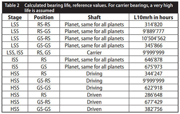
Mounting the planet bearings to the carriers induces a planet yaw torque that reduces the load capacity of an Orbitless gear-head. Mounting them to the planets avoids this yaw torque and results in an input load capacity that rivals a planetary gear-head while delivering approximately 8% more output power due to superior efficiency. Although planet bearing size is constrained by planets which must accommodate two non-coaxial bearings, a low rotation rate extends bearing life which is computed to be in excess of 5 years for the example gear-head described here.
An experimental comparison between a prototype Orbitless gear-head and an off-the-shelf planetary gear-head demonstrates dramatic improvements in power consumption due to reduced pitch velocity and fewer gear meshes. When operated at full torque with a load that ranges from 8-20W, the following loss reductions are recorded.
- Gear-head losses: 43%–59%
- Motor winding losses: 24%–45%
- Total system losses: 33%–46%
In addition, total input power, including power delivered to the load, is reduced by up to 33%. For a battery operated system, this means an increase in run time of up to 49%. 
References
- Jelaska, D. Gears and Gear Drives, Wiley, 2012.
- Lynwander, P. “Gear Drive Systems Design and Application,” Marcel Dekker Inc., 1983.
- Muller, H.W. Epicyclic Drive Trains, Wayne State Univ. Press, 1982.
- Musser, C.W. “Strain Wave Gearing,” U.S. Patent #2,906,143, 1959.
- www.micromo.com/products/brushless-dc-motors/brushless-dc-servomotors.
- www.micromo.com/products/drive-electronics/drive-electronics-datasheets.
- www.micromo.com/products/precision-gearheads/precision-gearheads-datasheets.
- Stocco, L.J. Orbitless Gearbox, Patent Cooperation Treaty, CT/CA2015/050423, 2014.
- Stocco, L. Orbitless Drive, ASME International Mechanical Engineering Congress & Exposition, Nov. 2016.
 Leo Stocco
 is the CTO of Oribitless Drives and the inventor of the Orbitless drive technology. He is a professor in Electrical Engineering at the University of British Columbia where he specializes in electro-mechanical design and medical instrumentation. He obtained his Ph.D. from UBC in the field of mechanical robot optimization and spent five years as the director of robotics at Integrated Surgical Systems in Davis California.
 Robert Gloeckner
 is R&D Engineer, Advanced Engineering, MicroMo Electronics, Inc.
This paper was first presented at the International VDI Conference on Gears 2017, Garching/Munich [VDI-Berichte 2294, 2017, VDI Verlag GmbH] and is reprinted here with VDI approval.