[advertisement]

March 1, 2018


Design Applications Mechatronics Rail Components Drives Gear Drives Gears Sensors Worm Drives Worm Gears Technical Articles Calculation Efficiency Failure Life Lubrication Power System Design Industry Trade Shows Hannover Messe MRO Maintenance Vibration

A New Standardizable Calculation Method to Predict the Efficiency of Worm Gear Drives

A New Standardizable Calculation Method to Predict the Efficiency of Worm Gear Drives

Manuel Oehler, Balázs Magyar and Bernd Sauer

Introduction

Within the scope of the research project FVA 729 I “Worm Gear Efficiency,” a physically based simulation method for the efficiency of worm gear drives was developed. This method is validated by experiments with different gear sizes and ratios. An extensive parameter study with the use of this simulation program was carried out to specify the magnitude of various influencing variables on the efficiency. The large parameter field for this study was created with design of experiments (DoE) to take into account a wide range of different parameter combinations. Based on the principle of similarity, the method of dimensional analysis was applied to derive an approximation equation for the efficiency in order to make the developed method accessible to broad practice. The derivation of this new, physically based formula using dimensionless influencing parameters is the object of this paper. The resulting tool allows calculation engineers to compare different drivetrain concepts with regard to efficiency. These easy-to-handle formulas can be incorporated into the standard DIN 3996.

Worm gearboxes are characterized by the large gear ratios that can be realized in a single stage, as well as by low-vibration- and low-noise-running behavior, compared to other gear transmissions. These positive properties, however, are associated with a lower efficiency compared to helical gearboxes, due to the high sliding velocities in the tooth engagement resulting from the intersecting axes. In order to be able to design efficient drive solutions, various transmission types and design variants must be comparable with each other in terms of the expected operating efficiency during the design phase. The approximation equations described in the German standard DIN 3996 (Ref.1) are based on quasi-stationary measurements of gearboxes with a gear ratio of i=20.5 and with a center distance of a=100mm. The transferability of the existing and partly standardized empirical formulas to other sizes and gear ratios is only possible to a limited extent. For this reason there is a need on the part of industry to expand the field of use of the calculation method in a broad range of sizes and gear ratios. The aim of this work is the development of a physically based simulation method which is verified by experimental results in order to reliably determine the efficiency of worm gear drives. Included in the investigations are various sizes, gear ratios and oil types, as well as stationary and transient operating conditions. The efficiency calculation of worm drives is based on theoretical principles, taking into account the different interactions of the influencing variables. This theoretical work is supplemented by random running trials and tribological investigations that provide input data for the calculations. This results in a physically based simulation model with which worm gearing can be investigated in a variety of ways. The target variables are, among other things, the local and the mean tooth friction coefficients, as well as the gearing and overall efficiency of the gearbox under test. The average gear friction coefficient can also be used to check the transmission for possible self-locking or self-braking.

Tribological Simulation

Magyar studied ZK-type cylindrical worm gears as part of his dissertation at the Institute of Machine Elements, Gears and Transmissions (MEGT) with regard to the tribological and dynamic behavior, both experimentally and simultatively (Ref.2). In his work a calculation model was developed based on the work of Bouché (Ref.3). Thus, the local tooth friction coefficients and the overall efficiency of worm drives operating in the mixed friction area can be determined by means of the TEHD theory in quasi-stationary operating conditions. The simulation model was verified with own test results. This calculation approach is the starting point of this work.

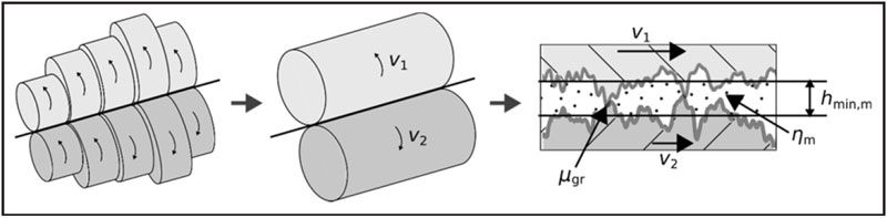
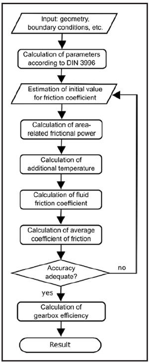
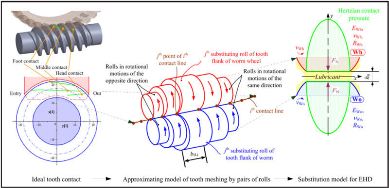
To calculate the locally variable tooth friction coefficients of worm gears, the theoretical contact lines are determined first (Fig.1,left). The calculation of the radius of curvature at the points of contact and the discretization of the contacting tooth flanks by rotating rollers follows (Fig.1,middle). In order to be able to model the kinematic conditions of the worm and worm wheel, the points in the contact zone are modelled with the aid of rotating rollers. Considering the kinematic behavior of the gears, the sliding and sum velocities in every point of the contact lines are calculated. The lubricating gap height is determined under the assumption of a Hertzian pressure distribution (Fig.1,right).

Simplified tribological modeling of the contacting teeth of worm gears
Figure 1 — Simplified tribological modeling of the contacting teeth of worm gears (Ref. 2).

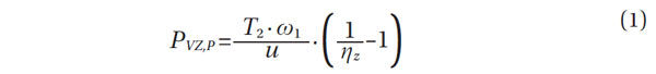
Knowing the film thickness of the lubricant and using pre-calculated division curves for the load-carrying contact ratio derived from a self-developed software, the rate of boundary lubrication can be calculated for each rotating pair of rollers. The heat conditions in the contact zone are determined in an iterative manner by simultaneously solving the differential equation for Fourier’s law of heat conduction and the simplified energy equation of the lubricant. With a known lubricant temperature, the viscosity and the fluid friction force dependent on this viscosity can be calculated for all pairs of rollers. Subsequently, the calculation of the coefficient of mixed friction follows, which corresponds to the local friction coefficient between the gears. A more precise description of the procedure of this method can be found (Ref.2). According to the knowledge of the local tooth friction coefficients, these can be averaged and thus the total efficiency of the gears ηz and the gear power loss PVZ,P can be calculated.

Share and save:


This article appeared in the March 2018 issue.


Read PDF

[advertisement]

Here, T2 is the output torque on the worm wheel shaft; ω1 is the angular velocity of the drive shaft; u is the tooth ratio; γm is the lead angle of the worm, α0 is the pressure angle, and μZ is the average coefficient of friction. In addition to the tooth friction losses, there are still further sources of loss in the worm gear (Ref.4).

For the calculation of the additional losses, existing methods, which are state-of-the-art, are used: The calculation of the bearing losses PVL is carried out according to the methods of the bearing manufacturers, the friction in the dynamic seals PVD is carried out according to Engelke’s model (Ref.5) and the churning losses of the gears PVZ,0 according to (Ref.6).

Validation by Experimental Results

For the validation of the tribological simulation software extensive experimental investigations are carried out with worm gear drives of different sizes and gear ratios. In the tests, ZK-type worm gears with two different center distances (a=40 and a=125mm) and two gear ratios (i=10 and i=60) are analyzed. In addition, all tests are carried out with two different types of lubricants. While the smaller worm gearboxes are from serial production, a new drive with a=125mm is designed especially for research purposes. For all experiments the same kind of materials (worm: 16MnCr5, worm wheel: CuSn12Ni) is used. The worm wheels of the smaller gearboxes are made of CuSn12Ni-GC (continuous casting) and the worm gears of the gearboxes with a=125mm are made of CuSn12Ni-GZ (centrifugal casting). The tests are carried out on the modular MEGT electrical wiring test bench. The basis of this test bench is two asynchronous machines with a maximum power of Pmax=30 kW.

The test bench for examining the worm gearboxes with a center distance of a=125mm is designed as shown in Figure 2. Here, the component’s drive motor (Eq.3), output motor (Eq.13) and test gearbox (Eq.7) can be seen. In addition to the torques and rotational speeds at the input and output shaft (Eqs.4,9), the temperatures are recorded on several non-moving components. Additionally, the temperature of the rotating worm wheel is transmitted by telemetry via a Bluetooth transmitter (Eq.8) and receiver. In order to reduce the torque at the output motor (Eq.13), a planetary gearbox (Eq.12) is built in the power flow between the latter and the test gearbox (Eq.7). The test bench for testing the transmissions with a center distance of a=40mm corresponds largely to the structure described above. Figure 3 shows an example of the validation results for the gearbox with center distance a=125mm and gear ratio i=10 for lubrication with polyglycol-based oil (PG) of viscosity class ISO VG 460. The comparison between the tribological simulation and the experiments shows very good agreement for both of the examined sizes. The German standard DIN3996 overestimates the efficiency by up to 4%, at an input shaft speed of 1,400min–1.

Sketch of the test rig setup for the worm gear drive with a = 125 mm.
Figure 2 — Sketch of the test rig setup for the worm gear drive with a = 125 mm.
Comparison of gearbox efficiency for a worm gearbox with a = 125 mm, i = 10,
lubrication with polyglycol ISO VG 460 at ?S = 60°C — as determined by tribosimulation,
experimentation, and DIN 3996 (Ref. 1).
Figure 3 — Comparison of gearbox efficiency for a worm gearbox with a = 125 mm, i = 10, lubrication with polyglycol ISO VG 460 at ?S = 60°C — as determined by tribosimulation, experimentation, and DIN 3996 (Ref. 1).

Approximation Equations

To apply the results of the described work in practice, approximation equations for the determination of the gearing efficiency by simple means are derived. In order to be able to find a suitable calculation rule, a detailed parametric study with the validated simulation program is carried out, thus creating a meaningful data basis. Based on this, the interactions between the different input variables and the efficiency of gearing are examined in order to be able to quantitatively describe them. The approximation equations for the determination of the efficiency of worm gear drives are devised under the guideline of finding a standardizedbut at the same time physically justifiedapproach that can be adopted in (Ref.1). For this reason many calculation bases and characteristic values (mean pressure between the tooth flanks σHm, mean sliding speed vgm, mean film thickness hmin.m, and average sliding distance sgm) are taken from the existing standard (Ref.1). Since in practice worm gears operate in the mixed friction area, an approach is used for the approximation equations described below, which considers both boundary and fluid friction in order to reproduce the physical circumstances in the mixed friction area.

The average friction coefficient in the worm gear unit μZ is thus composed of a proportion determined by boundary friction (boundary friction coefficient μGr) and a proportion determined by the fluid friction (fluid friction coefficient μFl). The division factor between the friction mechanisms is the load-carrying contact ratio ψ. While local tribological quantities are calculated with the tribological simulation from (Refs.2, 7) in order to be able to determine the coefficient of friction in the mixed friction area, a global approach with average characteristics is selected for the approximation equations. The transfer from local to global values is outlined in Figure 4. Influence variables such as the coefficient of boundary friction μGr, the velocities of the tooth flanks v1 and v2, the lubricating gap height hmin,m and the viscosity of the lubricant ηm are now no longer calculated for single discretization points, but are incorporated as global variables into the tribological consideration of the tooth contact.

Schematic representation of the procedure for the transfer from local (left) to global tribological parameters (right) through
simplification by reduction to a global replacement roller pair (middle) (Ref. 7).
Figure 4 — Schematic representation of the procedure for the transfer from local (left) to global tribological parameters (right) through simplification by reduction to a global replacement roller pair (middle) (Ref. 7).
[advertisement]

The load-carrying contact ratio ψ is calculated using the dimensionless film thickness λ. In order to calculate the dimensionless lubricating gap height λ, the average gap height hmin,m is divided by the combined root-mean-squared roughness Sq of both friction partners (worm Sq,1 and worm gear Sq,2).

In addition to the dimensionless film thickness λ, the deformation behavior of the two friction partners is decisive for the proportion of boundary friction. With a detailed contact simulation of real-measured surfaces, a relationship between the approximation of the solids and the proportion of the surfaces that are in contact with each other can be calculated. It is found that, in the case of contact calculation with different worn tooth flank surfaces that have been processed by the same manufacturing method, a similar profile exists of the curve describing the load-carrying contact ratio results independently of the root-mean-squared roughness Sq (Fig.5). This relation can be described according to (Ref.2) with an equation of the following form:

The coefficients a and b are determined by means of a curve-fitting method from division curves generated with different surfaces. Figure 5 shows the results of the contact calculation in the form of the division curves for the load-carrying contact ratio and a compensation curve.

Multiple dimensionless division curves for the load-carrying contact ratio from contact simulations of different measured tooth flank surfaces and compensation curve through all calculated values.
Figure 5 — Multiple dimensionless division curves for the load-carrying contact ratio from contact simulations of different measured tooth flank surfaces and compensation curve through all calculated values.

The coefficient of boundary friction μGr is determined as an integral parameter from friction coefficient measurements at a twin-disc test rig. These measurements are carried out using a combination of materials (steel 16MnCr5 and bronze CuSn12Ni) that are typical for power transmitting worm gear drives and representative surface structures. The additives and the temperature of the lubricant, the pressure between the friction partners, the slide-to-roll ratio (SRR) and the direction of rotation of the disks relative to each other (constant or counter-flow), are decisive influencing variables on the boundary friction coefficient, which is determined at very low hydrodynamic velocities. For the approximate calculation of the coefficient of friction between the gears, an average coefficient of boundary friction is required. The parameters of a simplified equation for the estimation of this mean boundary friction coefficient as a function of the mean pressure σHm must be determined separately for each selected lubricant:

The fluid friction coefficient μFl is determined from the shear stress of the fluid in the lubricating gap. This characteristic is calculated by the shear stress τFL relative to the mean pressure of the tooth flanks σHm.

The shear stress τFl is calculated according to the fluid model of Bair and Winer, taking into account a limiting shear stress of the fluid τlim (Eq.9).

In addition to the limiting shear stress of the fluid τlim, the mean sliding velocity vgm and the mean lubricating film thickness hmin,m, which can be calculated according to (Ref.1), are also required to calculate the shear stress in the lubrication film. Furthermore, knowledge of the mean dynamic viscosity ηm of the lubricant in the gap is necessary. The viscosity of the fluid depends essentially on pressure and temperature. The mean pressure between the tooth flanks σHm will be used as the pressure in the lubricating gap; the temperature in the gap must be calculated from the temperature in the oil sump ϑS and the flash temperature ϑflash due to the heat input caused by the friction in the contact zone. The flash temperature depends on the area-related frictional power and the mean sliding distance sgm, for which the following empirical relationship is used:

The thermal constant Cth was obtained using regression methods from the data base generated by the parameter study and is mainly dependent on the materials of the gears and the type of lubricant. The method for determining the lubricant temperature in the lubricating gap requires an average coefficient of friction, which is simultaneously the target value of the calculations, as an input variable. For this reason an iterative approach is required. This means that a starting value for the average coefficient of friction must be estimated and afterwards iterated until the deviation between the result and the incoming coefficient of friction comes down to a limit value. This approach is outlined in Figure 6 and explained in more detail in (Ref.7). The presented method for the approximate determination of the average coefficient of friction shows very good overall agreement with the detailed tribological simulation method (Fig.7).

Flow chart of the iterative procedure.
Figure 6 — Flow chart of the iterative procedure.
Comparison of the friction coefficient calculated with the tribological
simulation and the values determined by approximation equations.
Figure 7 — Comparison of the friction coefficient calculated with the tribological simulation and the values determined by approximation equations.

Here, the coefficient of friction determined by means of the described approximation equations is plotted over the coefficient of friction determined with the tribological simulation. In the range of μZ>0.04, the deviations between the two calculation methods are, for the most part, ΔμZ<0.005. The deviationsparticularly with very small coefficients of friction (μZ<0.03)can be attributed, for example, to the uncertainties in the calculation of the fluid film thickness according to (Ref.1).

Conclusion

In this work a physically based method for the tribological investigation of worm gears is presented. In order to derive a standardized calculation approach, average values instead of local parameters are used for the tribological considerationsthus greatly reducing the computational effort. A comparison of the tooth friction coefficients calculated using this easy-to-handle method with the more complex, local simulation shows good agreement.

Acknowledgments. This work was supported by the German Federal Ministry of Economics and Energy (IGF18275 N) within the framework of the cooperative industrial research and the Forschungsvereinigung Antriebstechnik (FVA project 729 I) (Ref.7).

References

  1. DIN 3996. Tragfähigkeitsberechnung von Zylinderschnecken-getrieben mit sich Rechtwinklig Kreuzenden Achsen. Berlin: Beuth Verlag 2012.
  2. Magyar, B. “Tribo-dynamische Untersuchungen von Schneckengetrieben,” Dissertation, Technische Universität Kaiserslautern 2012.
  3. Bouché, B. “Reibungszahlen von Schneckengetrieben im Mischreibungsgebiet,” Dissertation, Ruhr-Universität Bochum 1991.
  4. ISO/TR 14179-2. Gears — Thermal Capacity, Part 2: Thermal Load- Carrying Capacity, 2001.
  5. Engelke, T. “Einfluss der Elastomer-Schmierstoff-Kombination auf das Betriebsverhalten von Radialwellendichtringen,” Dissertation, Universität Hannover 2011.
  6. Changenet, C. and M. Pasquier. “Power Losses and Heat Exchange in Reduction Gears: Numerical and Experimental Results,” 2nd International Conference on Gears. (VDI Berichte 1665), pp. 603–613. Düsseldorf, VDI-Verlag GmbH 2002.
  7. Oehler, M., B. Magyar and B. Sauer. Schneckengetriebewirkungsgrade, Abschlussbericht FVA-Vorhaben Nr. 729 I: Frankfurt/Main, Forschungsvereinigung Antriebstechnik 2017.
Dipl.-Ing. Manuel Oehler studied mechanical engineering at the University of Kaiserslautern, Institute of Machine Elements, Gears and Transmissions (MEGT), graduating in 2014 as a Graduate Engineer.
Jun. Prof. Dr. –Ing. Balázs Magyar received his Ph.D. in mechanical engineering in 2012 at the University of Kaiserslautern, and then joined the University the following year as a junior professor of tribology. His current research interests include the tribology of worm gear drives, bearings and shaft seals. Magyar is now teaching machine elements and engineering tribology.
Prof. Dr.-Ing. Bernd Sauer holds a Ph.D. in mechanical engineering from Technische Universität Berlin. From 1987–1998, he has as chief engineer for various companies headed up their development departments in the high-speed rail industry. Since 1998, he has served as full professor and head of the Institute of Machine Elements, Gears, and Transmissions at the University of Kaiserslautern. His current research interests include the dynamics and tribology of bearings, seals and chain drives. Sauer since 2015 has led the Society of Product and Process Design at the Association of German Engineers (VDI).
[advertisement]