Advanced Lubricant Technology for Open Gear Applications
Lubricating greases are typically known for their use in a wide variety of applications such as rolling element bearings, automotive transmission joints as well as heavy duty chassis components; but can also be found very useful in the lubrication of gears. There are two types of gear families: the primary difference being open and enclosed gearboxes. The gears within a closed system are lubricated with grease within the system. Open gears are lubricated by grease or fluid separate from the piece of equipment. In 1938, AGMA published a tentative draft specification covering the lubrication of both open and closed gears (Ref. 1). This was approved by the AGMA Lubrication Committee in 1946. The most recent version of this standard was from 2016 and was re-issued in 2021 (Ref. 2). Independently of AGMA, there are now multiple specifications for lubricants, both liquid and lubricating greases for enclosed gearboxes. This paper will focus on the lubrication of open gears, utilizing both grease and fluid Open Gear Lubricants (OGL).
Mining, sugar, paper, textile cement and food production are just some of the applications that utilize OGLs that provide to meet stringent lubrication requirements that include increased base oil kinematic viscosity, high load-carrying, good antiwear properties, pumpability, environmental acceptability, low consumption rates, adequate corrosion protection amongst other secondary requirements (Ref. 3).
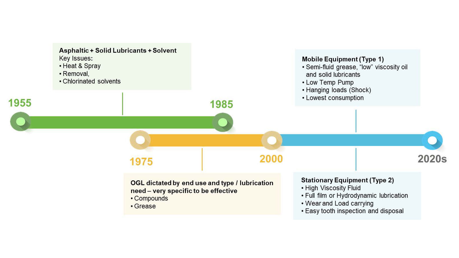
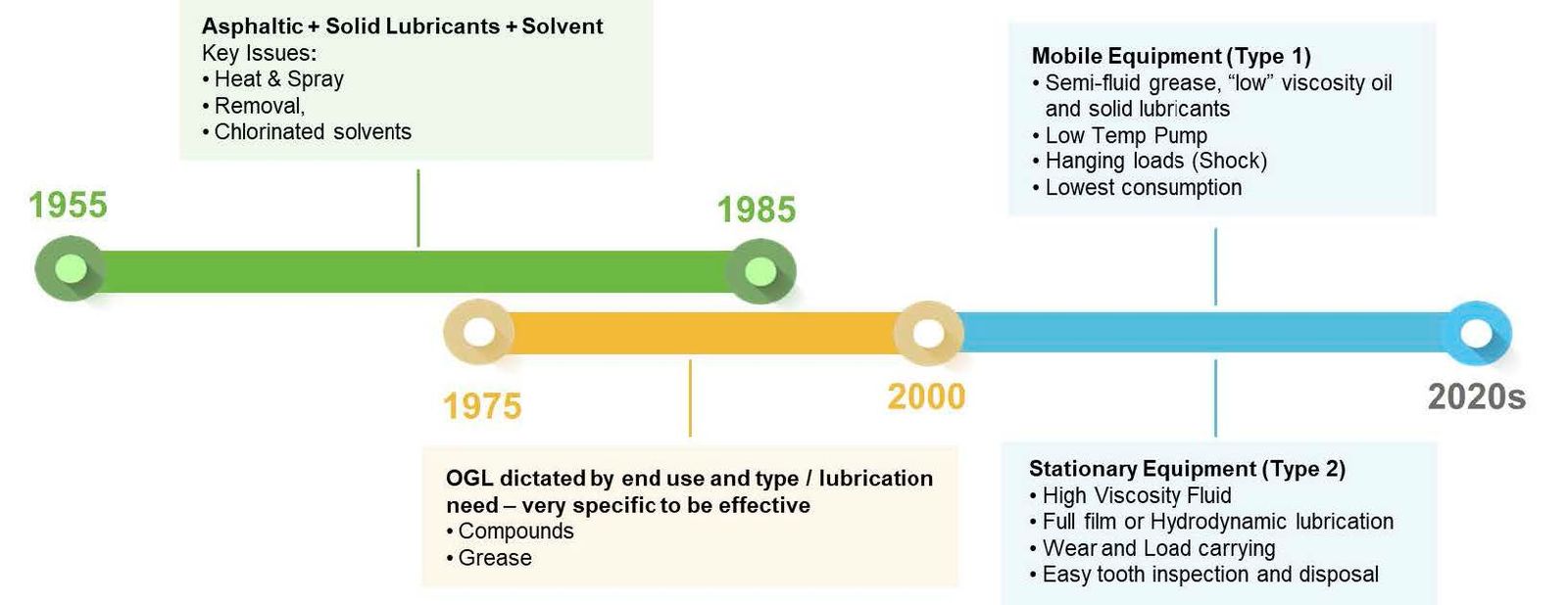
Since industrial applications demand stringent requirements for these lubricants, OGLs have evolved through time since their conception in the 1950s (Figure 1). Since their introduction, the traditionally applied OGLs were asphaltic type products which evolved into sprayable asphaltic cut back products. These OGLs were typically formulated with high kinematic viscosity mineral oils that contained high levels of asphalt or bitumen combined with a volatile solvent diluent.
Figure 1—Evolution of OGLs.
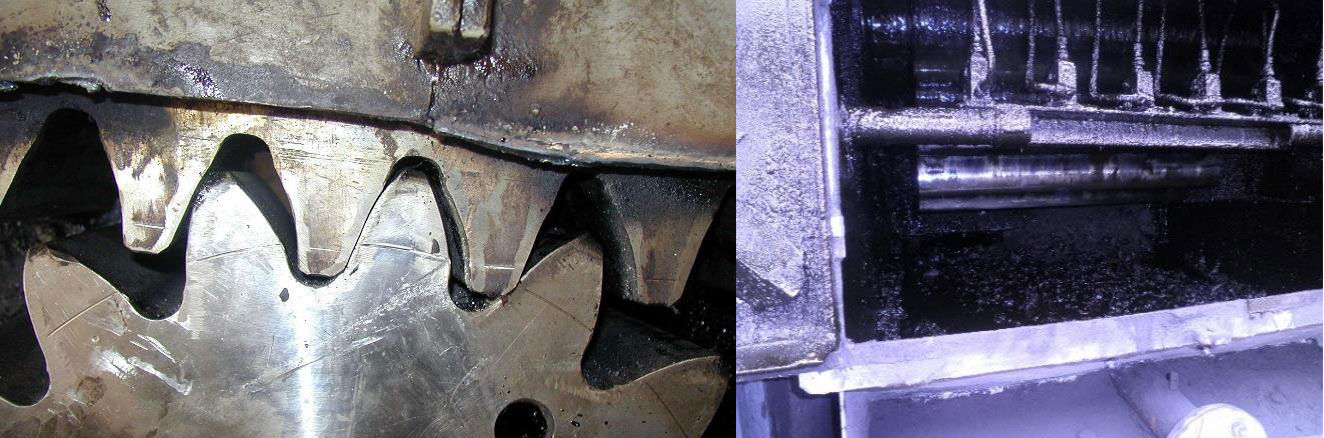
These lubricants were typically applied by spray systems and as the meshing action of gears began, the solvent would evaporate off, leaving behind a viscous lubricant. Cutback solvents were predominantly chlorinated such as 1,1,1-trichloroethane because they were rapid to evaporate, had high flash points and improved the efficacy of spray application. This type of OGL was popular from the 1950s until 1995 when the Montreal Protocol put a global ban on ozone depleting substances in commerce (Ref. 4). These OGLs also caused housekeeping problems because at higher temperatures they would readily oxidize, harden and cause lubricant buildup. At lower temperatures, these lubricants became difficult to dispense and would stiffen, crack and peel-off, leaving gears unprotected (Figure 2).
Figure 2—Asphaltic OGL applied to open gears.
Base Oil Selection
As open gear lubricants evolved, base oil selection became a crucial part in formulation. When selecting a base oil for OGLs, many variables need to be considered, such as: end use application, operating temperature and desired environmental profile base oil. Understanding the end use and whether they will be operating under fluid film, boundary or mixed lubrication conditions is very important. Traditionally, film thickness and strength were considered critical and drove the use of higher kinematic viscosity oils. One way to achieve higher kinematic viscosity base fluids is using polymers like polyisobutylene and synthetic base oils like Polyalphaolefins (PAO) as viscosity modifiers [5]. The use of high kinematic viscosity oils and polyisobutylene allows OGLs to better adhere to gears and prevent runoff during usage. More recently, new polymers like unique performance polymers (UPPs) have been found to be beneficial as viscosity modifiers and as base oils in other industrial gear oil applications (Ref. 5).
The evolution of open gear lubricants has produced two distinct types of OGLs—Type I and Type II. Type I, or grease type, OGLs were designed for mobile equipment typically found in mining and construction. Mobile equipment often has bidirectional operation, with frequent directional changes such as seen in hinge pins on backhoes, and in ring gears on excavators. An application issue is that they are often used in sub-ambient to sub-freezing point conditions. The type of greases used in these applications were often based on clay-thickened then more recently, aluminum complex thickeners (Ref. 6). Whatever thickener is used, the greases will contain chemically active additives for boundary lubrication protection, solid lubricants such as graphite, calcite, and molybdenum disulfide to help with surface separation under starved or parched lubrication. Diluent solvent may be required to aid application. Because Type I OGLs typically include a thickener, their consistency can be defined by an NLGI grade. The example Type I OGL specification can be seen in Table 1.
Property
Test Method
Requirement
Copper strip corrosion
ASTM D130, ASTM D4048;
24 hours @ 100°C
2a max
Rust protection
ASTM D1743
Pass
4-ball wear (without solvent)
ASTM D2266, wear scar diameter, 60 minutes @ 75°C
<0.70 mm
Weld point (without solvent)
ASTM D2596
>800 kgf
Load wear index (without solvent)
>120 kgf
Minimum base fluid kinematic viscosity Ambient temperature at point of lubricant application, °C (°F) -50–0 (-58–32) -20–40 (-4–104) 0–60 (32–140)
Table 1—Example of a Type I open gear lubricant specifications.
Type II OGLs
Type II OGLs or fluid OGLs are designed with stationary equipment in mind, such as sugar mills, cement kilns and grinding mills. These types of equipment operate in a single direction at slow operating velocities and warmer temperatures (50–80°C). The general requirements for an OGL in this application are high viscosities that support both boundary and fluid film lubrication. High kinematic viscosity fluids in these applications can enhance the OGL’s adhesiveness to the gears, especially at elevated temperatures. Like Type I OGLs, several industry-wide specifications have been developed by the American Gear Manufacturers Association (AGMA) (Ref. 7) as well as different original equipment manufacturers. While every end use is different, Table 2 highlights a typical example of the specifications required from a Type II OGL.
Property
Test Method
Requirement
Solids Content
Calculation
No solids
Kinematic viscosity at 100°C, cSt
ASTM D445
850 – 950
Copper strip corrosion
ASTM D130, 4 hours, 100°C
1B
4-ball weld point, kgf
ASTM D2596
800 kgf weld
4-ball wear scar diameter, mm
ASTM D2266
0.6
Table 2—Example of performance specifications for a Type II OGL.
End uses where Type II OGLs are utilized are opting more and more for solid-free fluids. The benefit to solid-free fluids is housekeeping and reduction of downtime. Equipment operators can easily inspect gears visually for damage which correlates to significant improvement in equipment reliability and a decrease in equipment shutdown.
Development of New OGL Technologies
Understanding the Importance of Base Oils and Polymers
Since OGLs rely heavily on base oil viscosity, the difference between viscosity improvers like, polyisobutylenes (PIB), polyalphaolefins (PAO) and unique performance polymers (UPP) needed to be better understood. We hypothesized that the UPP fluid would provide a lower coefficient of friction and better overall traction profile relative to the other base fluid types. Four base fluids were selected for a traction study and are highlighted in Table 3.
Component
Mineral, weight
PIB, % weight
PAO, % weight
UPP 40, % weight
Group II 600 N
100
80
Polyisobutylene
20
PAO-40
100
UPP 40
100
Kinematic viscosity at 40°C, cSt
117.6
454.4
428.7
420
Table 3—Base oils used for traction studies.
A base oil kinematic viscosity of 420 cSt at 40°C was targeted because of ease of testing. API Group II 600 N mineral oil was also selected as a baseline due to its inclusion in the PIB sample. Each of the oils was evaluated through MTM testing, which generated friction data at a range of slide:roll ratios. Each of the base fluids was loaded into the sample pot and was evaluated under the conditions shown in Table 4.
Test Parameter
MTM Test Condition
Load, N
72
Average contact pressure, GPa
1.25
Speed, r/min
2500
Temperature, °C
140
Table 4—MTM test conditions for base oil traction studies.
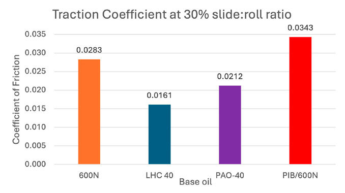
The temperature of 140°C was selected as a severe condition specifically to provide a worst case as a lubricant meshes between gears in field applications. Once each of the samples was loaded into the instrument, their traction coefficient was measured as the slide:roll ratio increased from 0–100 percent. Upon completion, traction coefficients were compared at a single slide:roll ratio and plotted in a bar graph (Figure 3).
Figure 3—Traction coefficient comparison at 30 percent slide.
Based on the base oil screen in Figure 3, it appears that treatment of the Group II 600N oil with polyisobutylene at even low weight percent, had a deleterious effect on the coefficient of friction. Given the OGL markets almost ubiquitous use of PIB as a viscosity improver, it is of no surprise that PIB-based OGL are not top-tier performing base fluids in industrial applications from a thermal perspective. PIBs have higher internal friction because of branching, which causes higher churning loss under fluid film lubrication, hotter running temperatures and lower efficiency. Based on industry knowledge, it was expected that the coefficient of friction would decrease when the PAO was used since it has lower internal friction during usage. Unlike the PAO, it was unclear how the UPP would perform in this study. Based on the results in Figure 3, the UPP provided the lowest coefficient of friction compared to the PAO which suggests that OGLs may see a boost in performance, especially at elevated temperatures, when UPP is used as the base fluid.
Type I OGL Development and Field Trial
The results of the base fluid traction studies in the previous section led to an investigation on how the three different types of base fluids (mineral/PIB, PAO and UPP) would perform as a Type I, or grease type, OGL. The grease type OGLs prepared for this study were lithium greases with a kinematic base oil viscosity at 40°C of ~2,000 cSt. The base oil compositions can be seen in Table 5.
Component
Mineral, % weight
PAO, % weight
UPP, %weight
Brightstock 150
68
PAO-100
87
Polyisobutylene (Mn2000)
32
13
UPP 100
80
UPP 2000
20
ASTM D445 Results
Kinematic viscosity at 40°C, cSt
2074
2123
2145
Kinematic viscosity at 100°C, cSt
99.1
145.5
154.5
Viscosity index
121
172
179
Table 5—2000 cSt (at 40°C) base oil formulations.
[advertisement]
It was noted that the base oil composed of strictly UPP had a higher viscosity index (VI), which may translate into better thermal stability of the finished OGL compared to the others (Ref. 8). A high kinematic viscosity index indicated that the viscosity of the fluid will not change drastically as temperature increases (Ref. 7). Moving forward, the base oils from Table 5 were used for lithium greases and blended with and combination of additives and lubricating solids, targeting a NLGI grade 0, which can be seen in Table 6.
Component
Mineral OGL, % weight
PAO OGL, % weight
UPP OGL, %weight
Lithium soap thickener
5
5
6
Polyisobutylene
87
(Mn 2000)
25
10
Brightstock (BS150)
53
PAO 100
68
UPP 100
62
UPP 1100
15
Additive Package
11
11
11
Solid lubricant
6
6
6
Table 6—Finished Type I OGL formulations.
The additive package in Table 6 includes additives for extreme pressure, antiwear, yellow metal corrosion and tackifier. Each of the finished OGLs were then evaluated for the properties required by the example specification from Table 1. The results from this testing can be seen in Table 7.
Property
Test method
Requirement
Mineral OGL
PAO OGL
UPP OGL
Worked Penetration
D217
n/a
400–430
400–430
400–430
Copper strip corrosion
ASTM D4048
2A max
1B
1B
1B
Rust protection
ASTM D1743
Pass
Pass
Pass
Pass
4-ball wear, wear scar diameter, mm
ASTM D2266
0.70 max
0.70
0.68
0.45
4-ball weld point, kgf
ASTM D2596
800 pass
800 pass
800 pass
800 pass
LWI, kgf
120 min
149.3
139.3
143.6
Table 7—Performance Testing on Experimental OGLs.
All three OGLs met the requirements of the defined specification, however, the UPP OGL had a smaller wear scar (ASTM D2266) compared to the other two OGLs.
To correlate the laboratory testing to industrial field applications, FZG testing was chosen as an additional metric of testing. FZG testing is used to evaluate the load carrying capacity of a fluid or grease via scuffing damage. Gear scuffing occurs when two teeth in a meshing gear set briefly adhere together and are then torn apart as the gears continue to rotate. This type of damage can lead to loss of contact geometry, leading to vibration, noise, and potential gear failure. As lubricant fluids thin under increased temperatures, load carrying additives become a necessity for gear protection.
In the FZG test, two specially designed gears are installed in a test chamber that will contain a specified amount of lubricant. These gears are manufactured to have very high sliding conditions, which creates an environment for scuffing to occur. The larger (wheel) test gear is connected to a shaft and motor, while a second smaller (pinion) test gear is connected to a parallel shaft containing a torsion coupling. A static load can be applied across the torsion coupling. These predefined loads are referred to as load stages and are the reported criteria once the scuffing failure limit has been exceeded. Most FZG tests run from load stage 1 to load stage 12 or failure, whichever occurs first. The extent of scuffing damage is assessed via visual inspection at the completion of each load stage (21,700 revolutions). The temperature at the end of each load stage is also observed.
Different FZG procedures can vary in motor speed, driver direction, gear width, gear temperature, and gear profile. Two common procedures are A/8.3/90 and A/2.8/50. A/8.3/90 typically follows the industry specifications ASTM D5182, CEC L-07 or ISO 14635 and uses A20 gears (20 mm thick), at 90°C starting temperature, rotating forward at a pitch line velocity of 8.3 m/s. A/2.8/50 has a lower velocity of 2.8 m/s and starting temperature of 50°C designed for testing gear greases, which follows ISO 14635-3 specification.
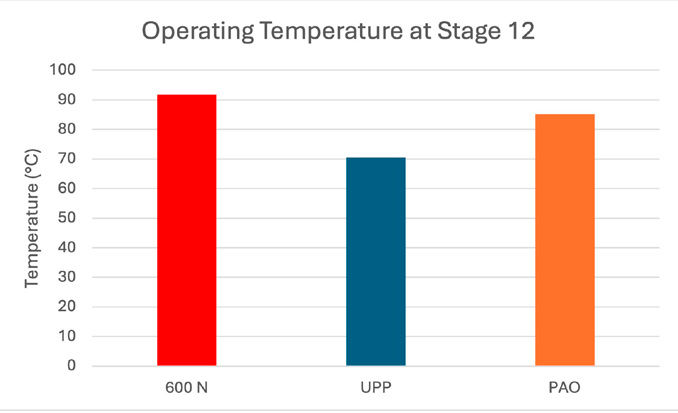
FZG A/2.8/50 (typical grease conditions) was executed examining the three samples (Table 5) over 12 load stages in the same testing stand. Using the ISO procedures, the gears are weighted after load stage 4. All three greases passed the load stage 12. Operational temperatures and energy consumption were measured using the Mineral OGL as the baseline material. Figure 4 shows the operating temperature of each gear at the end of load stage 12.
Figure 4—Temperature Reduction at FZG Stage 12.
Based on the results in Figure 4, it was concluded that the OGL made using the UPP base oil mixture operated 21°C cooler compared to the Mineral OGL. The UPP OGL also operated 15°C cooler compared to the PAO OGL. Thermal images of this testing were captured and can be seen in Figure 5.
Figure 5—Thermal images of mineral OGL (left) and UPP OGL (right) at FZG Stage 12.
The motor drives on the FZG stands were also capable of outputting the instantaneous power consumed by the motor every 10 seconds. This data can be plotted to form a power curve to illustrate power consumption over the course of the test. Integrating the power curve with respect to time provides the total energy consumed during a given period of time. In this case, trapezoidal integration was used to provide an approximation of the integral using the following equation:
where P is the instantaneous power consumed at the time step shown in the subscript. The energy values can then be compared between samples on a single given stand. This is best expressed as a percentage difference from a given baseline, as this type of analysis is relative to a given stand. The three OGL samples were run consecutively of the same stand and compared to the mineral oil (600N) baseline in Figure 6.
Figure 6—Power Consumption at Load Stage 12.
The results of the testing showed that the UPP based OGL consumed 20 percent less energy compared to the Mineral OGL and 5 percent less energy compared to the PAO OGL. In this comparison, UPP has demonstrated that it provides thermal and power consumption benefits compared to traditional OGL base oils.
The promising bench testing and mechanical testing allowed us to utilize UPP base OGL in a field trial to see how these grease type OGLs operated in real world, extreme, conditions. The field trial took place at a steel manufacturing facility in Germany. The grease type OGL was applied to the bearings of a casting ladle (Figure 7).
Figure 7—Image of a casting ladle at a steel manufacturer.
The basic composition of the field trial grease utilized a 7,000 cSt base oil composed of UPP and API Group II 600 N paraffinic oil. The composition and bench testing of this grease type OGL can be seen in Table 8.
Component
% Weight
Lithium complex/7000 cSt UPP base oil
84
Additive package
10
Solid lubricants
6
wt% Soap
7 – 9
Performance Results
Penetration, work 60 (ASTM D1403)
357
Dropping point, °C (ASTM D2265)
250
4-ball weld point, kg (ASTM D2596)
>800
4-ball wear scar, mm (ASTM D2266)
0.45
Corrosion protection
Pass
Table 8—Composition and bench test results of field trial grease OGL.
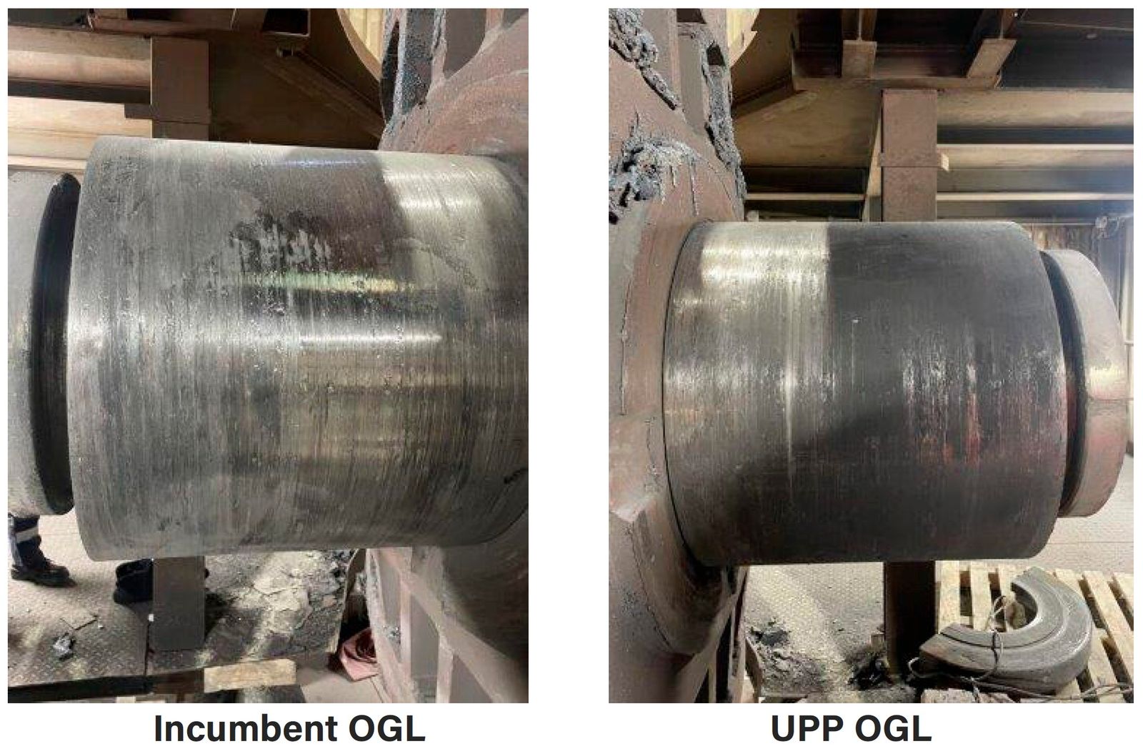
The field trial conditions included: 6-month duration; 2000 MT of weight of the ladle; temperatures of 80 –200°C; 220 melts (900 tilts). Since the conditions were going to be very severe, a high viscosity base fluid was designed so that it was more likely to remain on the equipment instead of running off. The steel manufacturer applied the experimental OGL to one bearing of the casting ladle and the incumbent to the other bearing. After the six-month duration of the trial, the casting ladle was deconstructed and the bearings were evaluated. Images of these bearings can be seen in Figure 8.
Figure 8—Images of bearings after six-month field trial.
The feedback that was received from the manufacturer was that the UPP OGL still remained on the bearing after the duration of the trial while the bearing that had the incumbent OGL was dry. This suggests that the high viscosity base oil that utilized UPP did remain where applied for the duration of the trial. It was also noted that there was minimal wear scarring on the bearing that used the UPP OGL. The bearing that used the incumbent OGL has substantial scarring.
Type I OGL Summary
Three grease type OGLs were formulated utilizing three types of base oils: mineral, PAO and UPP with an additive pack containing components for extreme pressure, antiwear and corrosion. The base oils that had kinematic viscosities around 2000 cSt at 40°C but had different kinematic viscosity index results. Because the UPP OGL had the highest kinematic viscosity index, it was thought that it would have beneficial properties at elevated temperatures compared to the other two OGLs. It appeared that the UPP based OGL did provide some additional antiwear performance. The three OGLs were then evaluated in the FZG A/2.8/50 which could be more easily correlated to real life applications in the field. This testing illustrated that the UPP OGL did provide a thermal benefit; in that it allowed for the test rig to operate at a temperature 21°C cooler compared to the mineral OGL. The FZG testing also demonstrated that the UPP OGL consumed 20 percent less energy when compared to the Mineral OGL on the same stand under the same operating conditions. The benefits of UPPs have also translated to top tier performance in the field. This has been demonstrated by the excellent load carry and antiwear capabilities of the UPP OGL used in the steel manufacturing field trial.
Type II OGL Development
Next in our OGL study, the effects of base oils in higher kinematic viscosity fluid type OGL were tested. We started with grease types and now wanted to validate that we saw similar effects in fluid types and determine if the thickener system contributed anything significant to the performance advantage presented in the UPP sample or the performance benefits were primarily attributed to the UPP. The Type II OGL fluids that were developed were blends of oils and kinematic viscosity modifiers that were then treated with the same. The formulations for these OGLs can be seen in Table 9.
Components
Mineral OGL, % weight
PAO OGL, % weight
UPP OGL, % weight
Polyisobutylene (Mn2000)
68
65
Brightstock (BS150)
24
PAO-100
27
UPP 2000
78
Group II 600 N
14
Additive package
8
8
8
Table 9—Type II fluid OGL formulations.
It is important to note that the PAO OGL required a heavy amount of PIB to meet the required viscosity requirements. Although PAOs have been shown to provide thermal stability, they do not offer high viscosity options like the UPPs. Since there are a wide range of UPP viscosity options, there is much more flexibility to formulations.
The individual requirements for this study are captured in Table 10 and are like the grease type requirements presented in the previous section Table 2. Load carrying was one stage lower. Based on the nature of these materials being fluid type, the additive pack is similar to additive package used in the grease study but not identical. Each of the Type II OGL fluids were evaluated for the properties seen in Table 10.
Property
Test method
Target
Mineral OGL
PAO OGL
UPP OGL
Kinematic viscosity at 40°C
ASTM D445
Report
30,400
20,000
16,500
Kinematic viscosity at 100°C
ASTM D445
850-950
877
861
926
Viscosity index
ASTM D2270
Report
195
228
258
Pour point, °C
ASTM D5950
Report
3
6
-9
Rust protection
ASTM D1743
Pass
Pass
Pass
Pass
Copper strip corrosion
ASTM D130, 100°C, 3 h
1B
1B
1B
1B
4-ball weld point, kgf
ASTM D2596
800
620
800
800
LWI, kgf
Report
128.8
144.4
145.2
4-ball wear scar diameter, mm
ASTM D2266
0.6
0.73
0.50
0.46
Table 10—Type II fluid OGL formulations.
Like the Type I OGLs, UPP again seems to have played a role in the reduction of the wear scar compared to the mineral oil OGL. It was also observed that the Mineral OGL does not perform as well as the PAO and UPP OGL in the load carry. These results suggest that base oil modifications and identity to a fluid type OGL may influence overall performance. An additional observation that was made was the decrease in pour point of the UPP OGL compared to the other two fluids, which suggests that the UPP OGL may be easier to handle.
In similar fashion to the Type I OGL studies, FZG testing was also conducted on the Type II fluid OGLs on the same test stand. The test conditions used were specifically for a fluid type—A/8.3/90. All fluids completed 12 load stages without scuffing. The end of test operational temperatures were compared, using the Mineral OGL as the baseline. The results can be seen in Figure 9.
Figure 9—FZG temperature reduction at load stage 12.
The UPP OGL completed load stage 12 at a temperature 15°C cooler compared to the Mineral and the PAO OGLs. The PAO and Mineral OGL seemed to perform identically which is likely due to the similar amounts of PIB needed to achieve their desired viscosities. While this test was being conducted, thermal images were again taken so that the temperature differences could be visualized in Figure 10.
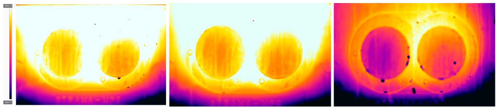
Figure 10—Thermal images of mineral OGL (left), PAO OGL (middle), and UPP OGL (right) at FZG load stage 12.
The color profile of these thermal images is different than the images of the Type I grease OGLs in Figure 5 because a different imaging software was employed. The images show that both the Mineral OGL and PAO OGL run at an elevated temperature in comparison to the gear box running in the UPP fluid OGL. The energy consumption data collected from this testing correlated to the thermal data as well.
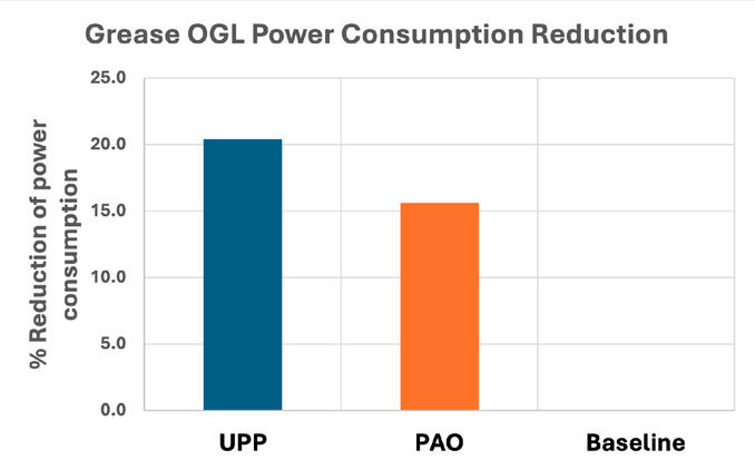
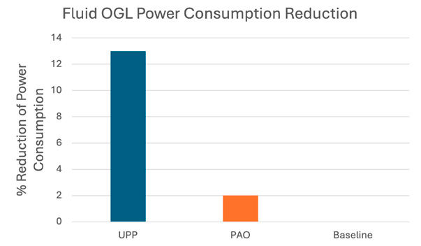
Energy consumption data calculation was executed as indicated in the previous section. The results from the FZG testing found that the UPP OGL consumed 13 percent less energy compared to the Mineral OGL and 11 percent less energy compared to the PAO (Figure 11).
Figure 11—Power consumption reduction at load stage 12.
Similar to the Type I OGL development, we wanted to translate the Type II development in the field applications. The first trial occurred at a sugar mill in North America where the OGL was designed for the open gear as well as journal bearings. The fluid OGL was applied to journal bearings (decided by the refinery) for the duration of one season of sugar cane refining. The conditions an OGL faces in sugar mill are extremely harsh and include: high temperature, high humidity, juice and water contamination, high presence of dry and wet bagasse as well as constant power washing. The fluid formulation that was introduced into this field trial can be seen in Table 11.
Component
% by weight
UPP/base oil blend
94
Performance additives
6
Performance Properties
Kinematic Viscosity @ 40°C
20,719
Viscosity Index
271
4-ball weld point, kgf ASTM D2596
620
4-ball wear scar, mm ASTM D2266
0.40
Table 11—Type II UPP OGL formulation and performance.
During the field trial, two main parameters were monitored: operating temperature and lubricant consumption. The UPP OGL was evaluated and compared with an incumbent OGL operating on a second mill in the same season and for the same duration of time. At the end of the refining season, the sugar mill reported its overall findings which can be seen in Table 12.
UPP OGL
Incumbent OGL
Average operating temperature, °F
74.1 (23.4°C)
84.2 (29.0°C)
Set lubrication interval at end of trial
18 minutes
10 minutes
Bearing appearance at end of trial
Minimal wear scarring
Catastrophic wear damage
Table 12—Results of sugar mill trial.
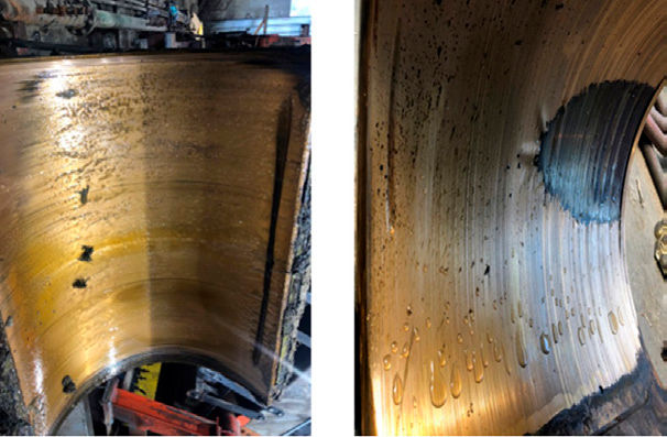
The sugar refinery communicated that the UPP OGL allowed them to reduce the lubrication interval which decreased lubricant consumption by 35 percent. They also reported that the mill with the UPP OGL operated 10°F cooler in comparison to the mill with the incumbent OGL. Lastly, they reported that upon inspection of the journal bearings at the end of the season; the bearing that was lubricated with the UPP OGL could be used for another sugar season. The pictures of the journal bearings at the conclusion of the trial can be seen in Figure 12.
Figure 12—Appearance of journal bearings at the end of trial.
After the successful trial at the sugar refinery, an opportunity to trial at a ball mill presented itself. The ball mills in need of a fluid OGL were located near a copper mine in Peru. The UPP formulation required higher load carry capabilities, so we selected the UPP formulation seen in Table 9. This UPP fluid OGL would be evaluated on two different ball mills. The details of the ball mills can be seen in Table 13.
Ball Mill 09
Ball Mill 10
Brand
Norberg
Citic Heavy
Size (diameter x length, m)
4.27 x 12
4.27 x 12
Mill speed (r/min)
14.6
15.7
Type of lubrication system
Double line
progressive
# of lubrication points
7
6
Table 13—Ball mill characteristics.
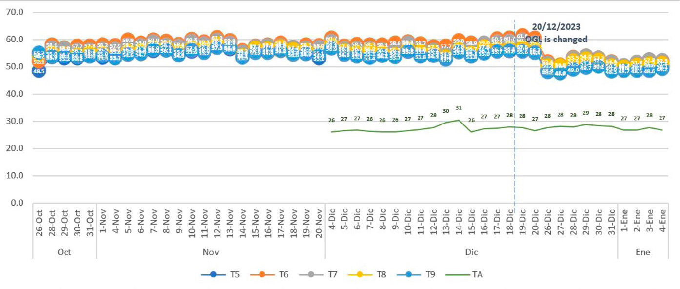
Unlike the sugar mill trial, both mills were lubricated with the incumbent OGL and temperature and lubrication consumption were measured. The UPP OGL was then cycled into both mills and the same parameters were monitored. Both mills’ operating temperatures were reduced by 5–6°C. The temperature reduction in ball mill 09 can be seen in Figure 13.
Figure 13—Temperature monitoring of ball mill 09 after introduction of UPP OGL.
This trial is still ongoing, however, the last reports from the mine site have reported that they have reduced the lubrication interval on both mills from 20 minutes to 25 minutes, while maintaining the reduction in operating temperature. The mine site has also reported that they have seen a 9.4 percent reduction in energy consumption on ball mill 09 and a 16.7 percent reduction in energy consumption in ball mill 10. The reduction in energy was based on the energy consumption while the incumbent OGL was in use.
Type II OGL Summary
The Type II OGLs, or fluid OGLs, were formulated using the same additive system across these samples so that base fluids could be compared directly. Both synthetic OGLs (PAO and UPP) were able to meet the specifications that were set in Table 10, compared to the mineral that struggled to meet the load carrying and wear specifications. It was also observed that the pour point of the UPP OGL was significantly lower which would lead to easier handling and application in the field in colder climates and end uses. Like the grease type OGLs, comparatively, the fluid OGLs performed similarly when in FZG testing. When UPP is used as a base oil, the corresponding OGL operates at a much lower temperature and consumes less energy compared to PAO and Mineral OGLs. Field trials in both a sugar mill and two ball mills have further demonstrated the outstanding performance benefits from UPP based OGLs. Reduction of lubricant use, reduction in operating temperatures, reduction in energy consumption and extended tool life are a result of UPP polymers and can be a substantial cost savings to the refineries.
Conclusion
In the development of new OGLs, both Type I and Type II, it was determined that base fluid selection was critical to performance. Early traction studies demonstrated that synthetic fluids, especially unique performance polymers such as UPP, decrease the coefficient of friction compared to mineral oil/polyisobutylene (PIB) blends, especially at elevated temperatures. This trend was then further observed and confirmed in both grease and fluid OGL through FZG evaluations. Based on this testing, it was believed that UPP based OGL, grease or fluid, would allow the end user to consume less OGL, operate at lower temperatures and potentially extend the life of the gears in their equipment. This hypothesis was further proven by the successful field trials at a steel manufacturer, a sugar mill and copper refining ball mills.
References
Fish, G., Clark, J., McCune, D., Hsu, C., “Technology for Enhanced Girth Gear Greases,” NLGI India 26th Annual Meeting, Kolkota, February 2024.
“Lubrication of enclosed and open Gearing” AGMA Lubrication standard 250.01 (1946) reproduced in the pre-amble to AGMA 9005-F16 (2021): www.agma.org
de Vaal, P.L., “Open-Gear Lubrication: Meeting Industrial Requirements using Laboratory Techniques” Tribotest Journal, 1998, Vol. 5, p. 79.
Samman, N., and Lau, S.N., “Grease Based Open Gear Lubricants: Multi-Service Products Development and Evaluation” NLGI Spokesman, 1998, Vol. 62, No. 9, p 34.
Clark, J., Dura, R.D., Fish, G., Nazario, C., Jacobs, M., and Zhao, H. “Enabling Technologies for Enhanced Open Gear Greases and Fluids”, Paper #2223 NLGI 89th Annual Meeting, Toronto Ontario, Canada, June 2022.
Lorimor, J.J., and Hsu, C., “Understanding Open Gear Lubricants: Product Design Considerations” Presented at the NLGI 79th Annual Meeting Palm Beach, FL June 9–12, 2012.
ANSI/AGMA 9005-F16 (2016) American National Standard Industrial Gear Lubrication.
ASTM D2270-10 (2016) Standard Practice for Calculating Viscosity Index from Kinematic Viscosity at 40°C and 100°C ASTM International, West Conshohocken, PA.