George Hunt, Applications Engineer, Micromo
DC motors possess linear relationships that allow for very predictable operation. For instance, if enough voltage is applied across the terminals of a DC motor, the output shaft will spin at a rate proportional to that applied voltage. You can take the ratio of the applied voltage over the rated voltage and multiply that number by the no load speed and get the running speed. Also, if you decide to measure and plot the current and torque, you will have a simple straight line indicating yet another directly proportional relationship. When torque demands increase, so does the current. Plotting the torque and speed together, you will find that only two points of data are needed. Those are the no load speed and the stall torque. The entire motion control world, including manufacturers and designers, depend greatly on the premise that all these linear relationships will hold true. And they do because the laws of physics do not change! However despite their simplicity, selecting a DC motor for an application can still be a daunting task. There are many other variables that must be taken into account including dimensions, load, duty cycle, environment, feedback considerations, etc. Perhaps decoding some of the mysteries of motor operation will shed some light on the selection process.
Going for simplicity with brushed motors. If your application demands a reliable, time-tested, low cost motor, then brushed DC motor technology may be what you're looking for. The key here is simplicity. A brushed motor is designed to run off of straight-line DC voltage and can even be connected directly to a properly sized battery. When a DC voltage is applied across the terminals of a brushed motor, a potential difference is achieved and current is induced into the windings on the rotor. The brushes allow this current to flow through a rotating mechanical switch called a commutator. The rotor windings act as electromagnets and while powered form 2 poles that terminate at the commutator segments. This entire assembly is known as an armature. While rotating the commutator allows the direction of the current to reverse two times per cycle. This permits the current to flow through the armature and the poles of the electromagnets attracting and repelling the permanent magnets that encompass the motor's inner housing. As the energized windings of the armature pass the permanent magnets, the polarity of the energized windings reverses at the commutator. This process is called mechanical commutation and only found in brushed motors. During the instant of switching polarity, inertia keeps the rotor going in the proper direction and allows the motor to continue turning. The result is power in its mechanical form measured in watts. Mechanical power is the product of torque multiplied by the rotational distance per unit time (or speed). Torque is the force vector component that rotates a load about an axis and is inversely proportional to speed (Eq. 1):
PMechanical = Mω (1)
Where,
P = Mechanical Power; M = Torque; ω = angular velocity
From the equation above, we see there is a price to pay for how much power a motor can deliver. The amount of current that flows through the windings, directly affects to the torque the motor can produce. Adjusting the supply voltage will force a proportional change in the motor's speed so the output shaft's angular velocity (speed) will have to be sacrificed as torque demands increase. There are also other factors that come into play such as losses. For example, static friction is defined as the friction torque a motor must overcome in order for the shaft to begin turning. Then there are brush contact losses caused by the friction of the brushes upon the commutator. Also, copper losses in the form of heat sometimes referred to as I2R losses play a role. Electrical power is represented in Eq. 2.
Pelectrical = I2R (2)
Where,
P = Electric Power; I = Current; R = Resistance
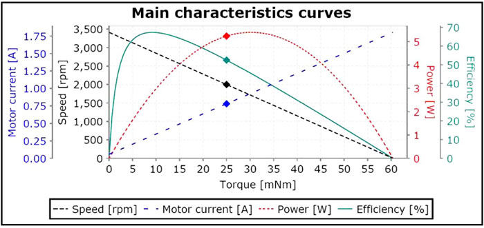
Although, when torque and speed are measured empirically, the resulting graph may not be perfectly linear in all cases. From Equation 1, however, we can see that both torque and speed are inversely proportional and that a linear relationship exists. Because of this, feedback may not always be necessary. Feedback is usually provided by an encoder, tachometer or resolver. It tells the servo system where the motor is and at what speed the shaft is turning. Taking all this into account, we can establish that a properly designed, closed loop servo system will have a predictable response to a controlled input. And with this directly linear relationship a servo can easily compensate for any unwanted changes introduced into the system; see Figure 1 for a plotted curve from a Faulhaber coreless DC motor; note specifically the linearity of the torque / speed component.
Figure 1 — Plotted curve from Faulhaber coreless DC motor; note linearity of torque/speed component.
Iron core brushed DC motors. Traditionally, the motion control industry has relied on iron core brushed DC motors for demanding applications. They are capable of achieving a very high torque due in part to their iron core construction. The rotor is usually a rigid design that not only provides a sturdy support for the windings, but also allows for excellent heat dissipation. That is the reason more current can be pushed through the windings when torque demands increase — it acts as a heat sink. Their low cost is yet another plus when project funding is limited. There are, however, some disadvantages to the iron core construction. For example, due to its heavy armature, overcoming the inertia can reduce a motor's acceleration capability. Higher rotor inertia limits the dynamic characteristics such as the motor's acceleration and stopping time. Another problem with the iron core rotor design is increased inductance. When running at high speeds the brushes will pass over the commutator's segments and imperfections. At each commutation point, when the brush breaks contact with a commutator segment, the energy stored in the motor winding as a magnetic field causes an arc or voltage spike between the brush and the commutator segment. This occurs not only during normal commutation but also in situations where the brushes "bounce" on the rotating commutator. At higher speeds, this effect can result in faster brush wear and electro-erosion. One solution is to utilize a precious metal commutator system. This type of system allows for motors to be manufactured much smaller, as a carbon graphite commutation system takes up much more space. The commutation signal will usually be cleaner as well. Since the voltage drop between brushes and commutator is generally small in precious metal systems, motors can be made to operate at lower voltages. However, due to a precious metal system's inability to self-lubricate, precious metal commutation can experience a long-term effect called "micro-welding." This effect can wear down the commutator's surface over time.
Coreless DC motors. The answer to some of the problems with iron core technology was addressed in the 1940s by Dr. Fritz Faulhaber with the invention of the coreless DC micro-motor (Fig. 2). This design opened up a whole new multitude of possibilities for space-constrained applications requiring high precision. These motors have a self-supporting, progressive, skew-wound, ironless rotor coil that has demonstrated incredible efficiency when compared to iron core motors. For the first time, DC motors did not require the use of iron laminations in the armature. Thanks to this construction the rotor is extremely light, yielding a low moment of inertia. This in effect allowed for faster acceleration, resulting in a much smaller mechanical time constant. Another benefit to coreless DC motors is that they can be manufactured in very compact sizes; which is why they excel in space- constrained applications. The rotor also rotates smoothly without cogging and the coreless DC motor's windings have very low inductance. All of these characteristics help reduce brush wear and prevent electro-erosion — thus increasing the motor's lifespan.
Figure 2 — Faulhaber-designed coreless DC micro-motor.
Unfortunately, however, with no iron laminations coreless motors are somewhat prone to overheating. In some instances a heat sink can be used to alleviate this problem. Also, cost would have to be factored into most applications as the high precision and repeatability of coreless DC motors comes at a bit of a price. These motors are designed for specific applications and would not be the best choice to use in most consumer products. The most common applications are large OEMs in industries requiring very high precision, primarily for medical, aerospace, military, robotics and automation. Some example products are aesthetic lasers, diabetic insulin pumps, collision avoidance scanners, and unmanned aerial vehicle (UAV) applications. These applications have demanding micro-positioning needs, dimensional constraints, and sometimes vacuum compatibility needs. Coreless DC motors seem to excel in situations where reliability, precision, longevity and repeatability are of the upmost importance.
For more information:
Micromo
14881 Evergreen Ave.
Clearwater FL 33762
Phone: (800) 807-9166
www.micromo.com
Reprinted courtesy of Micromo, a Faulhaber Group company.