GWJ Technology Offers Integrated Solutions for Gears in 3D CAD Systems

GWJ Technology GmbH has introduced new versions of its integration modules for Solidworks, Autodesk Inventor and Solid Edge. In addition to comprehensive tooth form output in 2D DXF or 3D STEP/IGES for various gear types, GWJ also offers integration modules for its calculation solutions eAssistant and TBK in various 3D CAD systems.
Using these CAD plugins, the various calculation modules, e.g., for cylindrical gears, gear racks, involute splines or bevel gears, can be started directly via a menu integrated in the CAD system. After successful design, recalculation or optimization, the gear teeth can then be automatically generated as 3D models directly in the respective CAD system. In this process, involute gears can also be cut directly on existing parts. The associated calculation information is saved with the component and can thus be called up again from the 3D component at any time. If the associated calculation is modified, the gearing already created can also be adapted on the basis of the new calculation.
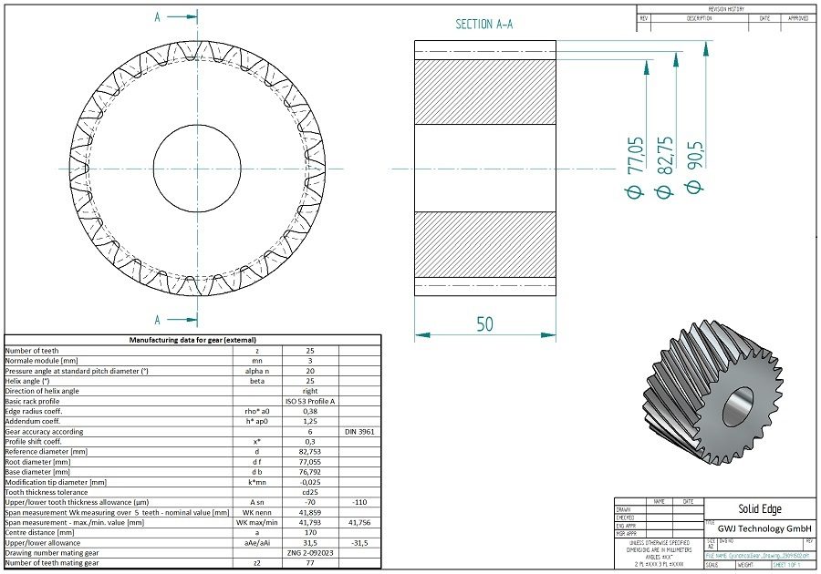
In the new versions of the CAD Plugins, additional rotation surfaces are now generated for tip, pitch and root circles. These can be used as support for the drawing derivations. In addition, the automatic generation of design tables with manufacturing data directly on a drawing is possible. This avoids transmission errors for the basic gear and test data and supports fast and convenient working. Depending on the user, the application and type of gears and their manufacturing method, the requirements are very different. Therefore, these tables can be customized.
Completely new and extended options are now available for configuring these tables with the most important gear data for manufacturing. These offer significantly greater flexibility than before. This means, for example, that numerical values coming from the calculation can be embedded directly in a text. Calculations are also possible directly in the templates, for example to output average values from minimum and maximum values. Furthermore, minimum and maximum values can also be written in one line. Furthermore, it is possible to place a graphic together with the table on the drawing. This can be e.g., symbolic representations or special additional information.
The new option of working with different templates for a specific gear type is also particularly advantageous. If several templates are available for the same type, the user can select the currently desired template from a listbox before the table is placed on the drawing. An individually created template can also be easily integrated into the list selection. Another configuration file is available for this purpose. No programming knowledge is required to customize the table templates and access to all parameters in the CAD transfer file is possible without any problems. The CAD transfer file as well as all other calculation files are freely readable XML files, which are practically self-explanatory for an average gear expert.


