A Guide to Gearmotors
10 considerations for long and efficient life
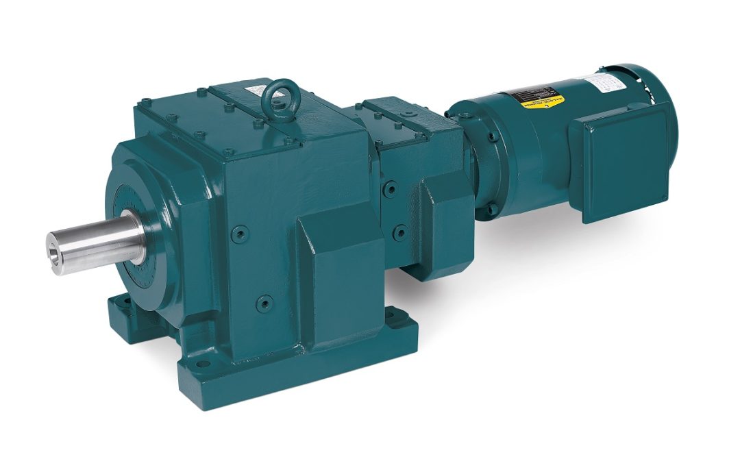
Possessing one of the most common arrangements, inline gearmotors such as this have the output in line with the motor. Image courtesy of Dodge.
Packing significant efficiency in its relatively small size, an electric gearmotor combines an electric motor with a gear reducer to decrease the motor speed and increase torque available at the gearbox output shaft. Gearmotors are used in processes to produce, manufacture, convey, package and store products used every day and are used frequently in small packaging applications due to their compact size. These units need care via preventive maintenance just like any asset used on a production site.
Our focus will be on general-purpose applications and the choices to best provide a long and efficient gearmotor life. Specific applications require additional consideration and ongoing maintenance.
What are the criteria for selecting the right gearmotor for the application? The main considerations are summarized below:
- Speed output
- Torque output
- Application running requirements and duty cycle
- Output configuration
- Output orientation / mounting position
- Environment
- Gear reduction selection
- Lubrication
- Gearmotor control requirements
- Design
1. Speed Output
What speed or speed range is required for the application? If the gearmotor is used to run a conveyor, the required conveyor feet per minute must be calculated through the drivetrain to determine the required gearmotor output rpm. If the gearmotor is controlled by a variable speed drive, the speed range of the gearmotor rpm required will need to be used for the design.
2. Torque Requirements
Torque is the force necessary to move a load. On a conveyor, the torque can be calculated based on the maximum load of material on the conveyor and the properties of the conveyor design. The gearmotor must have the torque output required to start and move the conveyor belt and material at the appropriate speed.
Torque demand is also an important consideration. Does the gearmotor see a high-loading situation at startup? Does the load have an impact or shock requirement to be considered? High starting load and/or shock/impact load will require additional service factors or other gearmotor design considerations for long life.
3. Application Running Requirements and Duty Cycle
What is the gearmotor’s required operating profile? Does it operate 24 hours per day and 7 days per week, or 8 hours per day and 5 days per week, or intermittently? Does the gearmotor operate a cyclic load such as an indexing conveyor? Understanding these factors and duty cycle, i.e., the time on and time off required, is necessary to select the right gearmotor.
Loads with high duty cycle, shock load, extreme operating temperature, and vibration should be addressed when selecting the solution. A higher class and service factor will offer mechanical design compensation to accommodate these load factors.

Used in a foam recycling mixer application, this gearmotor features a C-face to protect the motor from the oil and to provide a dry connection between the motor and the gearbox. In case of a motor failure, the facility can swap the motor without touching the gearbox. This unit has a speed output of 15 rpm and a torque output of 115,000 lb.in. Image courtesy of Motion.
4. Output Configuration
How will the gearmotor transmit the speed/torque to the load? Gearmotors can be provided with a hollow shaft, allowing the driven shaft to be inserted into the gearmotor output. A solid output shaft with a keyway is also common for mounting a sprocket and chain, pulley, and belt, or coupling to the load.
The output can also use a flange to mount the gearmotor to the load. Other configurations may have feet and be mounted on a base connecting to the load through the coupling, belt/pulley, or chain/sprocket.
5. Output Orientation Mounting Position
Where will the gearmotor output be oriented compared to the motor? The most common arrangements are inline and right angle. An inline gearmotor will have the output in line with the motor (see photo, page 14), while the right-angle version may have the output to the right or left, up or down when compared with the motor position. The mounting position refers to how the gearmotor will be mounted: will the feet/body be up, down, right or left? The mounting position must be known when selecting to ensure the internal lubrication is properly oriented for the gearing.
6. Environment
What are the environmental characteristics of the gearmotor location? Is the area inside, outside, clean, dirty, dusty, or wet? Is the atmosphere corrosive, hazardous, or requiring an explosion-proof (XP) rating? What is the ambient temperature range at the gearmotor’s location?
Gearmotors are available in different enclosure types, including open steel units for clean areas, totally enclosed units with protective coatings, and stainless-steel construction. Explosion-proof units must be specified based on the XP environment and installed/operated per the area code requirements.
Ambient temperature considerations may result in using different lubrication and grease for the temperature range. The right design will ensure long operating life. Extreme temperature environments include freezers, ovens, foundries, and furnaces.
7. Gear Reduction Selection
Gearmotor gearing types vary in design and efficiency, including planetary, helical, worm and others. Each gearing type provides differing levels of efficiency and is related to the configuration of the gearmotor (right angle, inline, shaft mount, etc.).
In general, the higher the efficiency, the longer the life expectancy. Choosing the highest efficiency gearing means less heat generated during operation and lower mechanical interference, translating to longer gear life, lubrication life and system life.
Some applications require a specific type of gearing to provide the needed load characteristics. These application load considerations include backlash, positioning, impact, and duty cycle.
8. Lubrication
Various lubricants are available for gearmotor gearing. The two main types are mineral oil and synthetic-based lubricants. The lubricant’s purpose is to coat contact surfaces, reduce friction and transfer heat away from the gearing.
The correct lubricant characteristics depend on the application. Lubrication varies by viscosity and additives depending on temperature, gearing and application requirements.
Choose synthetic lubricant for the longest life and best lubricating properties. It will provide the best reliability for your gearmotor, along with regular preventive maintenance checks to ensure the lubricant is functioning properly and at the right level. The lubrication must be changed at the recommended interval to maximize the gearmotor’s life.
9. Gearmotor Control Requirements
AC gearmotors are typically run with variable frequency drives (VFDs), soft starts or motor starters. DC gearmotors usually run with a DC drive. AC VFDs and DC drives offer the best control of the gearmotor.
A variable frequency drive will provide controlled starting acceleration, varying speed control, and controlled deceleration. This control reduces motor starting load and mechanical shock to the gearmotor and the load. Drives also provide speed control with the capability to match the load speed to process flow and maximize system efficiency.
Operating speed range is important when selecting the right gearmotor and drive. Motors vary in their capability to run on a drive. Some AC motors are not rated for operation on a VFD. Their construction may not allow for proper cooling under full speed or provide insulation rated for VFD operation. Consider the speed range required for the application and confirm that the gearmotor is rated to run the highest and lowest speeds needed on a drive.
Soft starts are an option for AC gearmotors. A soft start limits the power available to the motor during the acceleration, taking more time to reach full speed. The “soft starting” reduces the mechanical starting shock on the load and gearing, improving system reliability.
In contrast to a VFD that can change the running speed, the soft start will run the motor only at full speed. A soft start with an integral run/bypass contactor will disengage the soft start power electronics when running at full speed. This helps extend the life of the soft start. Ensure the soft start is rated for the starting characteristics of the load and duty cycle.
Motor starters are an option for AC gearmotors that provide full-voltage across-the-line motor operation. The motor will start as quickly as possible and run at full speed. Motor starters are a simple, cost-effective control choice. However, the quick starting to full speed adds wear to the gearing and load.
10. Design
At their core, gearmotors are a combination of a gearbox and a motor. While some gearmotors are neat, compact packages with the smallest overall length, the manufacturers have designed each piece integral to each other so if a maintenance problem exists, it impacts the whole unit. Another approach is to combine two separate units and make a gearmotor (see photo, left). That is, if one takes a gearbox with a C-face or coupled input and combines it mechanically with a standard NEMA or IEC motor, this design still qualifies as a gearmotor.
Each design (the integral unit vs. the combined unit) has its pros and cons when reviewing their use and application. The compact integral design allows for a smaller footprint and use in tight locations. It also provides for one inventory SKU and requires minimal setup. In contrast, the combined design consists of the gearbox and motor representing two individual SKUs, which can cause mounting issues when a coupling design is used. However, if one piece of the unit fails, it can be replaced quickly as the separate parts are more readily available, and only that section is required. Both gearmotor designs provide similar performance, yet their mounting requirements and availability could impact which makes the most sense for the application.
In summary, gearmotors are critical components of operations throughout industry and can provide years of efficiency with the right choices and planning. Understanding and accounting for an application’s load characteristics combined with the topics addressed above can help to provide a lasting solution when applying gearmotors. It may be wise to have a third-party specialist review the application and give additional insight, but the information in this guide will be a good start.
Related Articles
Related Events

-
December 11, 2024
-
Power Density Progress
December 2, 2024 -
CCTY Tackles Humanoid and Industrial Robot Development
September 13, 2024
-
The Future of Power Manufacturing, Warehousing, and Logistics
October 28, 2024 -
5 Ways to Save Money Through Ultrasonic Analysis
December 11, 2024
-
The Future of Power Manufacturing, Warehousing, and Logistics
October 28, 2024 -
5 Ways to Save Money Through Ultrasonic Analysis
December 11, 2024 -
Operational Improvements
December 11, 2024


